





— Download —
 Consumer hotline +8618073152920
WhatsApp:+8615367865107
Address:Room 102, District D, Houhu Industrial Park, Yuelu District, Changsha City, Hunan Province, China
All products

Plan a NiuBoL soil moisture sensor for agriculture around soils, root zones and valve areas. Review NBL-S-THR interfaces and field checks, then request a layout review.
Tel/WhatsApp:+8615367865107
Email:Arvin@niubol.com +Nearly 100 partner companies in more than 75 countries. We are committed to providing high-quality, practical products to meet your needs and help you solve problems. Our products comply with international standards and are certified with ISO, CE and RoHS.Product Details
Quick Answer: Select a soil moisture sensor for agriculture together with the area it must represent. Soil texture, rooting depth, irrigation pattern and valve layout determine whether one point is informative or misleading. The NiuBoL NBL-S-THR provides continuous soil moisture and temperature measurements for a compatible controller or logger; a farm deployment should establish representative monitoring zones before deciding the final probe quantity.
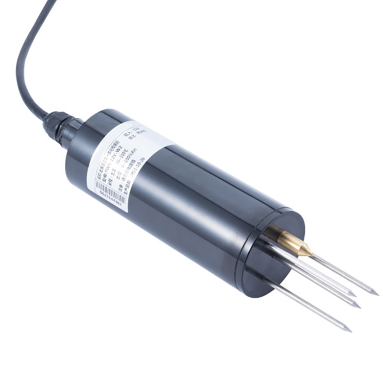
The cylindrical point probe measures soil dielectric response and reports a moisture value together with soil temperature. It is suitable for a defined sensing location rather than a direct measurement of the average water content of an entire field. Select the electrical version to match the farm's acquisition equipment.
| Parameter | NBL-S-THR configuration |
|---|---|
| Soil moisture span | 0-100%; resolution 0.1%; stated accuracy +/-3% |
| Soil temperature span | -50 to 100 degrees C; resolution 0.1 degree C; accuracy +/-0.5 degrees C |
| Supply | 12-24 VDC |
| Output versions | RS485 Modbus RTU, 4-20 mA or 0-5 V, selected when ordering |
| Power | Approximately 0.3 W |
| Operating temperature | -40 to 80 degrees C |
| Probe protection | IP68; field joints and acquisition equipment require separate protection |
| Cable arrangement | Specify length, jacket suitability and termination for the field route |
The 0-100% span is an instrument scale, not a statement that every agricultural soil can contain 100% water or that 50% means half the plant-available water remains. Interpret readings using the selected soil-water method and local conditions. The 0.1% increment also does not establish +/-0.1% field accuracy.
Soil texture, crop, slope, irrigation method and valve layout define whether points can share control logic. One sensor should not silently represent several unlike fields.
A monitoring zone describes land with sufficiently similar soil, crop and water response for a measurement to be useful. A valve zone describes land watered by the same controllable hydraulic circuit. They can overlap, but they are not automatically identical. The distinction determines whether the project needs another observation point, a hydraulic change or simply a different interpretation.
| Field arrangement | Deployment decision |
|---|---|
| Two contrasting soil types under one valve | Monitor the contrasting conditions separately. Extra sensors reveal the difference but cannot create independent watering without a hydraulic change. |
| Similar soil served by different emitter layouts | Check each layout's wetting response before treating one point as representative of both. |
| A local depression or leaking emitter within an otherwise uniform block | Use a representative point for routine management; investigate the anomaly separately rather than letting it control the block. |
| Different crops or growth stages on similar soil | Review root depth and management targets separately even if the soil calibration is shared. |
Before requesting a soil moisture sensor for agriculture, mark soil changes, valves and crop areas on one plan. Add known pressure or distribution problems. A point count based only on hectares can miss these divisions, while a large number of probes beside the same access road can repeat one unrepresentative condition.
Select depth from crop roots and the question being asked. A shallow point can show wetting quickly; a deeper point can show recharge or drainage. Multi-depth points are often more useful than repeating one shallow depth.
In drip irrigation, depth alone is insufficient. Record the horizontal relationship to the emitter and plant as well. A point beneath a dripper can respond much earlier than a point near the edge of the wetted volume. Decide whether the point is intended to indicate recharge in the active roots, the arrival of a pulse or movement below the managed layer.
For sprinkler or pivot irrigation, avoid wheel tracks, visibly unusual compaction and field margins when the purpose is representative crop monitoring. If the purpose is to investigate those locations, label them as diagnostic points rather than blending them into the routine zone average. Keep the question attached to the location.
Match measurement depths to the crop's active roots and monitor contrasting soils separately where they need different irrigation management (University of Minnesota Extension). The field arrangement must also account for the actual valve layout and irrigation pattern, rather than following a depth rule without checking what the point represents.
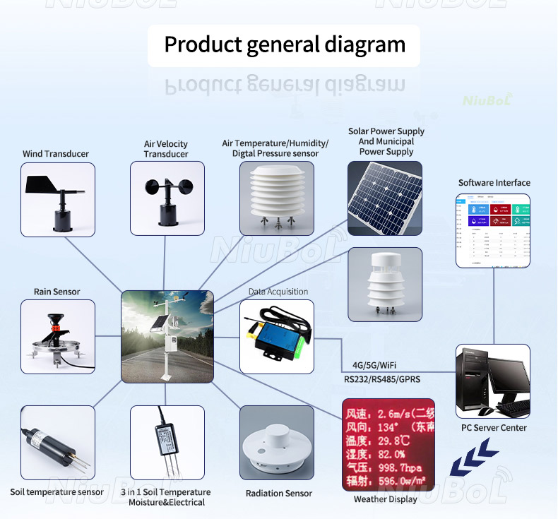
A solar panel, radio antenna or equipment cabinet may need an open, accessible location that is not the correct soil-monitoring point. Route a suitable sensor cable from the representative soil to the acquisition location where practical. Moving the probe to the cabinet merely to shorten a cable can change the quantity the project is observing.
RS485 reduces analog channel count and preserves digital values; 4-20mA is straightforward for dedicated PLC inputs; voltage requires attention to grounding and loss. Confirm the exact ordered model and scaling.
The sensor supplies measurements; the logger provides recording, and a gateway provides any required remote connection. For RS485 Modbus RTU, specify addresses and the delivered channel map with the receiving equipment. For analog versions, identify the separate moisture and temperature inputs. A remote dashboard is useful only after its tags are tied to the correct physical points.
The diagram above shows possible sensor and communication components, not the contents of one probe. Soil conductivity, pH and rainfall require their own appropriate channels if the management plan needs them. Do not infer those measurements from the presence of a multi-parameter monitoring diagram.
Start with representative and contrasting locations that can answer the zoning question. Log the existing irrigation schedule and actual delivery while the probes observe the response. A pilot should reveal which points behave similarly and which differences have a physical explanation before automatic control is enabled or the final network is purchased.
Record a pre-irrigation baseline, apply a known event, observe rise and redistribution, and compare with soil inspection and emitter performance. Repeat when crop roots or irrigation hardware change.
Inspect a flat or unusual trace at the field point. A blocked emitter, probe outside the wetted region, poor soil contact and a failed electrical channel require different remedies. Do not apply a numerical offset to make two traces match before checking whether they should describe the same water conditions.
When comparing two locations, retain their identities rather than averaging immediately. If the drier location repeatedly differs because of soil or distribution, an average can conceal the area requiring attention. Decide whether the response calls for a separate management zone, emitter maintenance or another reference point.

Air gaps, stones and loose backfill alter dielectric response. Install in representative soil, protect the cable from cultivation and record the exact relationship to emitter or drip line.
Mark the buried point and cable route so cultivation, harvest and repairs do not move the probe unnoticed. Protection must not change irrigation or create a small fenced-off soil environment unlike the surrounding crop. Keep joints accessible where possible and provide strain relief at exposed transitions.
Review the point after emitter replacement, deep cultivation, a changed crop or a revised root-zone objective. A sensor may still produce stable numbers while no longer representing the intended management area. If relocation is necessary, record the change and compare the new position before presenting the resulting trace as an uninterrupted record from the old point.
Send NiuBoL the crop, soil groups, valve layout, proposed depths and emitter relationships, together with the receiving interface and cable distances. Identify whether the purchase is for point probes, a multi-depth monitoring arrangement or a complete acquisition package. Request accessories and installation support against those locations rather than ordering an unexplained number of sensors.
If automatic watering is required, define the controller and hydraulic scope separately. The field plan establishes what the measurements represent; the controller must then decide when a zone may run, for how long and under which interlocks. Those decisions should not be hidden inside a sensor-only quotation.

Base the count on meaningful soil, crop and irrigation differences, plus the depths needed to answer the management question. There is no universal hectares-per-sensor rule. Use a pilot to determine whether additional points capture different behavior or merely repeat an existing observation.
It can receive them, but it cannot water the soil types independently. If their requirements differ, the project needs an agreed compromise, a changed schedule or separate hydraulic control. Adding measurements alone does not solve that limitation.
Only when that position answers the intended question. A point directly below the emitter can confirm early wetting but may not represent the wider root zone. Choose and record depth and horizontal offset together, then verify the response during a known cycle.
No. It indicates the soil-water condition at the probe under its measurement method. Crop, root distribution, soil-water retention and salinity affect interpretation. Do not label an arbitrary percentage as a universal stress threshold.
This configuration provides moisture and temperature. If conductivity is needed, specify a suitable additional or combined probe. Keep the parameters and model identities clear in the quotation and logger rather than inferring EC from a moisture channel.
The cabinet's exposure and access requirements can differ from representative soil conditions. Select the measurement point first, then design a suitable cable or acquisition arrangement. A shorter route is not useful if the resulting point describes a field edge instead of the crop.
Review it after irrigation changes, cultivation, crop changes, probe movement or unexplained shifts in response. Retain the original point identity and mark any relocation so the monitoring history does not silently combine different soil positions.
A soil moisture sensor for agriculture becomes useful when its location, depth and valve relationship are understood. Use the NBL-S-THR as an identified point measurement, test representative and contrasting areas, and let the field response determine the final deployment. A clear site plan gives NiuBoL and the integrator a practical basis for selecting probes, acquisition and installation scope.
Sensors & Weather Stations Catalog
 Agriculture Sensors and Weather Stations Catalog-NiuBoL.pdf
Weather Stations Catalog-NiuBoL.pdf
Agriculture Sensors Catalog-NiuBoL.pdf
Water Quality Sensor Catalog-NiuBoL.pdf
Related recommendations
 Multi-Depth Soil Sensor RS485
 TDR Soil Moisture Sensor
 Pyranometer Solar Radiation Sensors
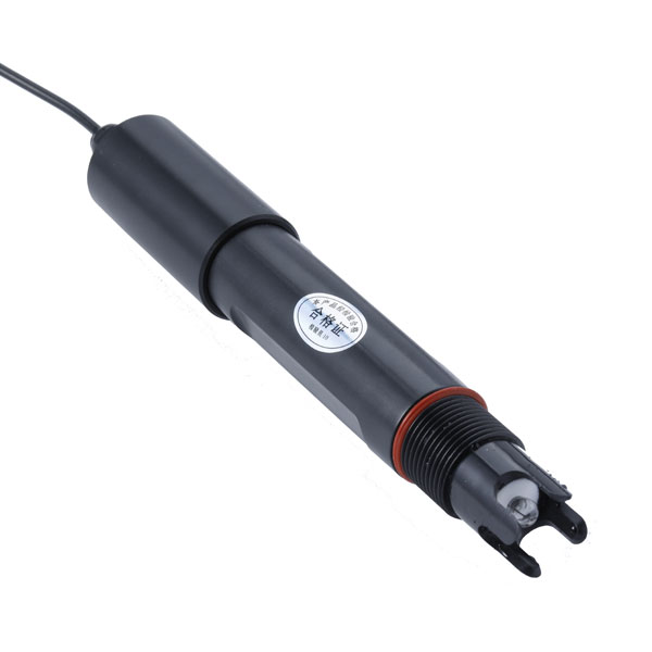 Soil ph sensor
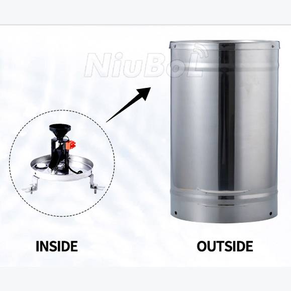 Tipping Bucket Rain Gauge
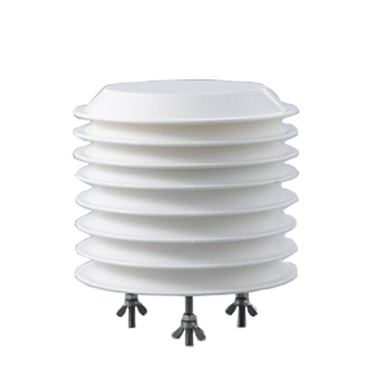 Air Temperature and Humidity Sensor


Screenshot, WhatsApp to identify the QR code
WhatsApp number:+8615367865107
(Click on WhatsApp to copy and add friends)

