





— Download —
 Consumer hotline +8618073152920
WhatsApp:+8615367865107
Address:Room 102, District D, Houhu Industrial Park, Yuelu District, Changsha City, Hunan Province, China
All products

Compare NiuBoL soil moisture sensors for irrigation and field monitoring. Review content versus tension, probe depth and controller inputs before selecting a system.
Tel/WhatsApp:+8615367865107
Email:Arvin@niubol.com +Nearly 100 partner companies in more than 75 countries. We are committed to providing high-quality, practical products to meet your needs and help you solve problems. Our products comply with international standards and are certified with ISO, CE and RoHS.Product Details
Quick Answer: Soil moisture sensors do not all measure the same quantity. Dielectric probes estimate water content, tensiometers measure soil-water tension, and resistance-based devices require their own interpretation. Select the measurement that answers the irrigation or research question before selecting the output. The NiuBoL NBL-S-THR is a moisture-and-temperature option for continuous monitoring; it does not add EC, pH or nutrient measurement simply because those factors also affect soil management.
The project may need to start irrigation, stop irrigation, verify water penetration, compare treatments or document drought response. Those purposes do not necessarily use the same depth, interval or sensor type. Define the decision, crop stage and management zone before comparing catalogues.
Dielectric sensors respond to the soil's apparent permittivity and are often calibrated to volumetric water content. Tensiometers report how tightly water is held, which can align well with plant availability but needs a different interpretation. Electrical-resistance methods are inexpensive in some formats yet can be influenced by salinity and electrode condition. The outputs should not be treated as interchangeable percentages.
| Technology | Measurement basis | Selection question |
|---|---|---|
| Capacitive or FDR dielectric probe | Electrical response related to apparent soil permittivity | Is the calibration suitable for the soil, salinity and required water-content interpretation? |
| TDR dielectric probe | Propagation or reflection of an electromagnetic pulse | Does the selected probe meet the field accuracy, contact and acquisition requirements? |
| Tensiometer | Soil-water tension within the instrument's working range | Does the control method use tension, and can staff service the water-filled instrument? |
| Electrical-resistance method | Resistance of the sensing arrangement, with method-specific conversion | How are salinity, temperature, electrode condition and maintenance addressed? |
Do not compare accuracy percentages across these methods without checking the quantity and reference. A tension reading in kPa cannot be inserted into a controller expecting a water-content percentage. Converting tension to content requires a soil-water retention relationship, not a universal electrical scaling factor.
Water availability also depends on more than total water content. Two soils at the same percentage can hold water differently, and dissolved salts add another aspect to plant response. Choose the primary moisture measurement and add other channels only where the management question needs them.
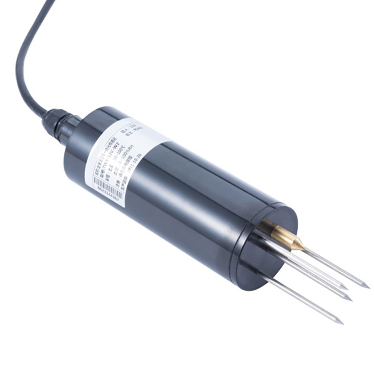
The NBL-S-THR soil moisture sensor uses an electromagnetic pulse and soil dielectric response. Its cylindrical probe provides moisture and temperature observations from the installed sensing position.
| Parameter | NBL-S-THR configuration |
|---|---|
| Soil moisture | 0-100%; 0.1% resolution; +/-3% accuracy |
| Soil temperature | -50 to 100 degrees C; 0.1 degree C resolution; +/-0.5 degree C accuracy |
| Supply | 12-24 VDC |
| Output versions | RS485 Modbus RTU, 4-20mA or 0-5V |
| Analog load limits | Current: 250 ohms maximum; voltage: 1 kohm minimum |
| Power consumption | Approximately 0.3 W |
| Operating environment | -40 to 80 degrees C |
| Probe protection | IP68 |
The moisture accuracy needs the applicable reference and test conditions when setting field acceptance. Do not interpret the 0.1% increment as 0.1% field accuracy. The temperature measuring range also does not extend the complete probe's -40 to 80 degrees C operating interval.
IP68 applies to the probe, not automatically to an added cable joint or the logger. Confirm the required cable and connection arrangement for the ordered installation. Use a separately specified sensor if EC, salinity, pH or another soil quantity is required.
A shallow probe can confirm that an irrigation pulse started but may not show whether water reached deeper roots. A deep probe can reveal drainage but respond too late for short-cycle control. Many projects use at least two depths: one in the active root zone and another near its lower boundary. The exact depths depend on crop, soil profile and irrigation method.
Divide the site by soil profile and irrigation behavior before deciding how many measurement points to buy. One point in each meaningful management zone can be more informative than several points beside the same access path. Within a drip zone, identify the relationship to the emitter and the intended root region.
For a layered soil, select positions that can distinguish water entering the active roots from water moving below them. Do not automatically average the shallow and deep probes: that average can hide a dry upper layer and a wet lower layer. Retain the separate traces and use a combined calculation only when its physical interpretation is valid.
Insert the sensing rods into close contact with representative soil and avoid creating an oversized disturbed pocket. A horizontal installation from an exposed profile face can help preserve the layer being investigated. Restore the excavation carefully and record the depth and relation to the irrigation hardware.
Before calling a flat trace a failed sensor, inspect whether water should have reached that position. A point beyond the wetted region may remain stable while a nearby point responds rapidly. Confirm contact and location as well as power and data acquisition.
A layer water-storage calculation requires a volumetric water-content basis and a layer thickness that the observation reasonably represents. For a uniform representative layer, a change in stored water is Delta S = 1000 x Delta theta x Z, where theta is a volume fraction, Z is layer thickness in metres and S is millimetres.
For example, a change of 0.03 m3/m3 across a representative 0.30 m layer corresponds to 9 mm of water storage. That is an illustrative calculation, not a recommended irrigation dose or a statement that every sensor represents a 30 cm layer.
If the instrument only provides an unvalidated percentage scale, establish its volumetric meaning before applying this calculation. For multiple soil layers, use representative values and thicknesses for each. A point change cannot, by itself, quantify the storage change of a heterogeneous root zone.
Water applied at the surface is not necessarily all retained in that layer. Runoff, drainage, nonuniform application and crop uptake affect the balance. Pair the sensor record with irrigation delivery and rainfall information when investigating where the water went.
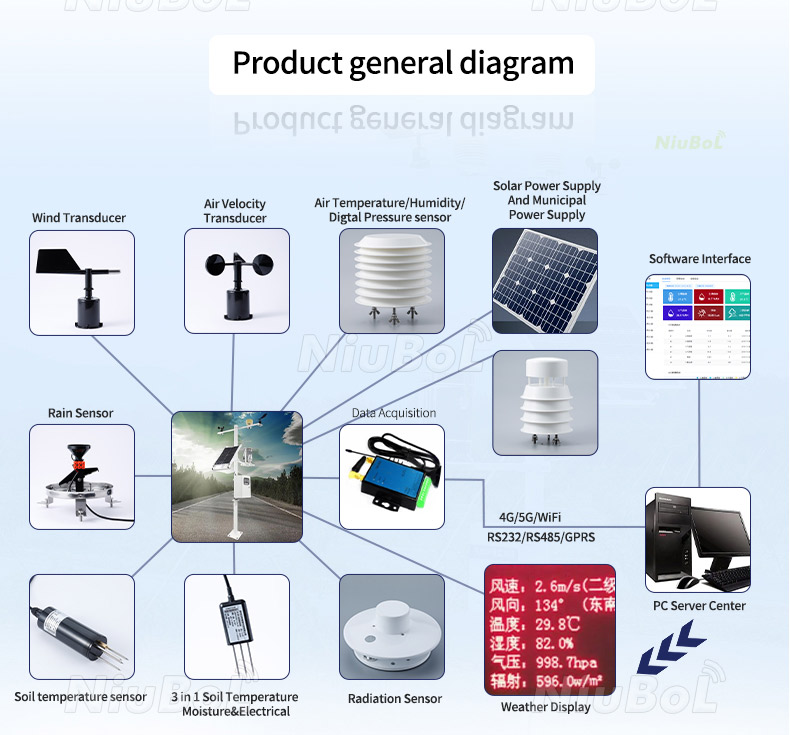
The monitoring diagram below illustrates optional soil and weather inputs with local acquisition and remote communication. It does not mean that one moisture probe measures every illustrated parameter.
Factory calibration provides a defined starting point, but soil texture, density, organic matter, stones and salinity affect the field relationship. If absolute water content drives research or contractual acceptance, compare readings with an agreed local reference method. For routine control, stable repeatability and validated thresholds may be more valuable than a broad generic accuracy claim.
Choose comparison points that represent the intended soil and water states. Keep sample volume, depth and timing identified; a small probe volume can differ from a nearby bulk sample. Where gravimetric measurements are converted to volumetric content, retain the bulk-density basis used.
Compare wetting and drying sequences, not only one value immediately after watering. A probe may agree at one point and still behave differently as the soil changes. Investigate salinity, texture, density and installation before applying a universal correction across all management zones.
Start irrigation thresholds from the selected crop and soil method, then check them against observed root-zone behavior and actual delivery. A threshold validated for a tensiometer or a different soil-water scale should not be copied into a dielectric percentage channel.
RS485 allows addressed sensors and direct digital values but needs a register map and disciplined bus design. A 4-20mA loop is straightforward for many PLCs and long dedicated channels. Voltage signals are convenient for shorter runs with compatible inputs. Include cable, surge protection, logger ports and power consumption when comparing total cost.
For the NBL-S-THR RS485 configuration, use Modbus RTU at 9600 baud, eight data bits and no parity; match the delivered stop-bit setting and allow more than 1000 ms between communications. Identify temperature and moisture separately and apply the appropriate data conversion.
In the two-parameter data format, raw 272 represents 27.2% for the moisture field. Treat the invalid or missing marker 0x7FFF as a status condition before applying the numeric conversion. Turning it into an enormous moisture percentage and then clipping it to 100% can make a failed point look fully wet.
For analog versions, specify which input carries each quantity and test both scales. A temperature midpoint and a moisture midpoint have different meanings even when both use a current signal. Inspect the delivered wiring arrangement before connecting the controller.
Use separate start and stop thresholds, minimum run times and delays for water movement. Reject stale or impossible data and define a safe fallback schedule. One failed sensor should not leave a high-value crop permanently irrigating or permanently dry. Manual override and flow confirmation remain important.
During commissioning, verify actual water flow as well as the controller command. A valve-open state with no delivery is different from a soil point that has not yet responded. Conversely, a wet sensor does not prove that a stuck valve has closed. Keep delivery feedback and the moisture decision distinct.
For selection, give NiuBoL the required quantity, soil or substrate, root layers, expected salinity, irrigation method and receiving input. Include whether the project needs point trends, a validated storage calculation or automatic control. A compatible data logger or gateway can carry the records onward once the measurement method is established.

A dielectric probe can be appropriate when its calibration and field performance support the required water-content interpretation. TDR and FDR labels alone do not establish interchangeable accuracy. Evaluate the actual probe, soil conditions and reference method.
No. Tension and content are related through the soil's water-retention behavior. Use an appropriate relationship for the soil and management method rather than a fixed conversion shared across all fields.
No. This configuration provides soil moisture and temperature. Select additional or different probes where salinity, conductivity or pH is part of the monitoring objective.
Not automatically. The example assumes a representative volumetric change over a defined layer. Actual irrigation scheduling also needs the target water state, application performance, rainfall, drainage and crop demand.
They can observe different layers and stages of a wetting event. Check roots, irrigation geometry and soil profile before diagnosing a fault. Keep the separate values rather than averaging away a meaningful difference.
Recognize the invalid marker before scaling, flag the observation and invoke the controller's defined fallback. Do not convert a missing value into zero or a clipped 100% reading that could drive an inappropriate irrigation action.
Run the selected probe in representative soil, compare it with an appropriate reference, observe an irrigation sequence and verify units, invalid-data handling and water delivery. Test the actual controller and record export rather than the sensor display alone.
Select soil moisture sensors by the quantity and decision required, then validate their location, field response and receiving configuration. A percentage is useful only when its meaning is clear. Send NiuBoL the soil conditions and irrigation measurement requirement to review a suitable sensor arrangement.
Sensors & Weather Stations Catalog
 Agriculture Sensors and Weather Stations Catalog-NiuBoL.pdf
Weather Stations Catalog-NiuBoL.pdf
Agriculture Sensors Catalog-NiuBoL.pdf
Water Quality Sensor Catalog-NiuBoL.pdf
Related recommendations
 Multi-Depth Soil Sensor RS485
 TDR Soil Moisture Sensor
 Pyranometer Solar Radiation Sensors
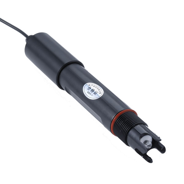 Soil ph sensor
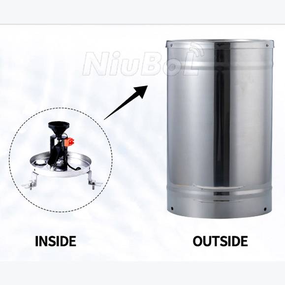 Tipping Bucket Rain Gauge
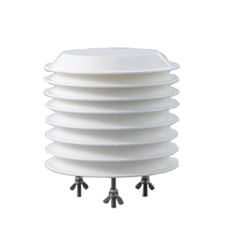 Air Temperature and Humidity Sensor


Screenshot, WhatsApp to identify the QR code
WhatsApp number:+8615367865107
(Click on WhatsApp to copy and add friends)

