





— Download —
 Consumer hotline +8618073152920
WhatsApp:+8615367865107
Address:Room 102, District D, Houhu Industrial Park, Yuelu District, Changsha City, Hunan Province, China
All products

Integrate a NiuBoL 7-in-1 ultrasonic weather sensor in a compact station. Check seven-channel acceptance, shared exposure and RS485 acquisition before requesting a quote.
Tel/WhatsApp:+8615367865107
Email:Arvin@niubol.com +Nearly 100 partner companies in more than 75 countries. We are committed to providing high-quality, practical products to meet your needs and help you solve problems. Our products comply with international standards and are certified with ISO, CE and RoHS.Product Details
Quick Answer: This NiuBoL 7-in-1 ultrasonic weather sensor combines horizontal wind speed and direction, air temperature, relative humidity, barometric pressure, piezoelectric rainfall and illuminance. The 12 VDC configuration communicates through RS485 Modbus and has 0.3 W average power consumption. Select it for a compact monitoring point only when the shared location provides useful exposure for all required channels. Commission the seven measurements individually; a successful serial reply does not validate the complete station.

| Channel or item | Specification |
|---|---|
| Wind speed | 0-40 m/s; 0.01 m/s resolution; +/-(0.5 m/s + 3% FS) accuracy |
| Wind direction | 0-359 degrees; 1 degree resolution; +/-3 degrees accuracy |
| Air temperature | -50 to 100 degrees C; 0.1 degree C resolution; +/-0.5 degree C accuracy |
| Relative humidity | 0-100% RH; 0.1% RH resolution; +/-5% RH accuracy |
| Barometric pressure | 500-1100 hPa; 0.1 hPa resolution; +/-1.5 hPa accuracy |
| Rainfall | 0-8 mm/min intensity range; 0.01 mm resolution; +/-10% accuracy |
| Illuminance | 0-200000 Lux; 1 Lux resolution; +/-10% accuracy |
| Power and communication | 12 VDC; 0.3 W average; RS485 Modbus; 9600 baud |
| Assembly operating environment | -40 to 80 degrees C; 0-95% RH |
| Housing and cable | ABS housing; IP65; 2.5 m standard cable |
Keep these limits together when specifying a replacement. A different seven-parameter assembly may use a different supply, pressure span, light increment or wind accuracy. The parameter count alone does not establish electrical or measurement equivalence.
The temperature channel's measuring interval is not the assembly's permitted operating interval. The 100 degrees C measurement endpoint does not extend the 80 degrees C operating limit. Similarly, the humidity channel's 100% RH endpoint does not establish that the complete device may be wetted or immersed.
On a 40 m/s full scale, the 3% FS wind term is 1.2 m/s; adding 0.5 m/s gives a 1.7 m/s error allowance under that expression. The 0.01 m/s output increment is therefore not an accuracy claim of 0.01 m/s. A project needing a tighter wind tolerance should evaluate a suitable alternative configuration before accepting this one.
A compact housing reduces separate supports and cable runs, but the surroundings still determine which air, light and rainfall reach the instrument. Survey the proposed mounting point with its final solar panel, antenna and bracket in place. Space left around a bare sensor may disappear after the rest of the mast is assembled.
Wind needs unobstructed airflow; the air channels need ventilation without nearby heat sources. The light channel needs the intended view, while the rainfall surface needs direct exposure without drips from equipment above it. A crossarm can shade the light channel and disturb wind even when it does not touch the housing.
For road, campus or distributed environmental monitoring, one compact point may meet the observation objective. In a greenhouse, a wind-exposed position above the structure will not automatically represent crop-zone air below the roof. Define which conditions the station should represent before treating all seven channels as equally suitable for control.
An integrated unit is attractive for compact deployments, but a reference meteorological site may need different mounting heights and exposure for wind, precipitation and air temperature. Separate instruments also allow one channel to be replaced without disturbing the rest of the station. Choose integration for deployment efficiency and separate sensors when the observation method requires independent exposure or performance.
For a network, test one complete sensor and logger combination before bulk installation. Freeze the Modbus map, polling interval, units and alarm rules, then clone the approved configuration. This prevents small integration differences from becoming a fleet-wide data-cleaning problem.
The rainfall channel senses raindrop impacts rather than collected-water bucket events. Use rigid mounting, restrain the cable and avoid nearby vibration and splash. Do not accept the rainfall calibration by tapping the housing or pouring an arbitrary water volume over its surface; neither establishes a known depth of natural rainfall.
The 0-8 mm/min specification describes an intensity range, equivalent to 0-480 mm/h. It is not a daily storage limit. Establish the returned rainfall quantity, its accumulation period and reset behavior in the selected firmware before assigning daily totals or interval intensities in the logger.
The light channel reports Lux. A PV project requiring irradiance in W/m2 needs an appropriate solar radiation sensor; a crop-light project requiring photon flux needs a suitable photon measurement. Relabeling Lux or applying one fixed conversion does not supply either quantity.
During acceptance, compare rainfall over aligned events and illuminance in a matching plane without temporary shadows. A weather app's regional rain total or a light meter held at another angle is not a direct check of the installed channel. Record the comparison conditions before considering a correction.
| Channel | Practical acceptance check |
|---|---|
| Wind speed | Compare a suitable reference in comparable airflow and over the same averaging interval; check m/s conversion. |
| Wind direction | Verify the physical direction mark and the receiver's direction convention before applying any offset. |
| Temperature | Compare in colocated, equilibrated air; inspect radiation exposure and nearby heat sources. |
| Relative humidity | Compare at the same air point and temperature; investigate wetting and restricted ventilation. |
| Pressure | Use matching units and the same station-pressure or sea-level-reduced basis. |
| Rainfall | Check rigid exposure, the returned quantity and reset behavior; align event totals with an appropriate comparison. |
| Illuminance | Check Lux scaling and compare the same light plane without obstruction or a temporary shadow. |
Begin with a bench check that confirms identity, power and seven correctly labeled values. Complete the exposure checks after field installation. A plausible temperature result does not prove that the rainfall multiplier or pressure definition is correct.
Keep short-term electrical checks distinct from measurement acceptance. An injected or simulated input may test the receiver, while a colocated reference tests a different part of the measurement. Neither should be recorded as a complete seven-channel calibration unless the agreed procedure actually covers that scope.
Supply 12 VDC at the sensor after cable loss. Configure the receiver for the delivered address, serial format and individual data definitions. Use 9600 baud for this configuration, and confirm the remaining serial settings and permitted polling interval with the ordered device before commissioning the network.
Do not copy the register sequence from a three- or five-parameter sensor because the housings look similar. Give every returned value an explicit parameter name, unit, conversion and status. Check a complete record at the PLC, RTU or logger, then again at the remote application.
Separate measurement timing, logger sampling and remote upload. A platform that receives an update every few minutes may still need local records at a shorter agreed interval. Retain whether wind values are instantaneous, averaged or calculated extremes; a network timestamp alone does not identify the underlying measurement period.
Each variable has its own failure pattern. A blocked or contaminated impact surface can affect rainfall; shade affects illuminance; solar heating and poor airflow affect air temperature; a loose north reference affects wind direction. A communication heartbeat only proves that the device answered. It does not prove that every environmental channel is representative.
Use plausibility rules in the logger. Flag values outside the stated range, a direction channel that never changes, rainfall during a clearly dry inspection period, or a temperature step that coincides with power restoration. Keep quality flags separate from the measured number so missing data is not stored as zero.
Because seven channels share one housing and cable, keep at least one configured spare for important networks. Record the Modbus address and logger mapping before replacement. After changing the unit, verify every register rather than checking wind speed alone.
Inspect the exposed surfaces for bird contamination, dust, insects and physical damage. Check bracket tightness and north orientation. Service frequency should follow the site rather than a fixed universal interval. Coastal salt, agricultural spray and roadside dust can require more frequent inspection.
After replacement, test the complete channel list and remove inherited corrections that no longer apply. Recheck direction alignment, pressure basis, light exposure and rainfall reset configuration. An unchanged address does not establish that the replacement has the same firmware definitions or measurement offsets.
For purchasing, distinguish the sensor assembly from the complete station. Mast, solar supply, enclosure, local storage and onward communications need their own specification. At 0.3 W average, the sensor represents approximately 7.2 Wh per day before logger, communication and supply losses; do not size a remote station from that sensor-only figure.
The diagram below illustrates a broader monitoring network with optional instruments. Those separate wind, radiation and soil channels are not additional measurements included in this seven-parameter assembly. A compatible logger or gateway handles acquisition and the selected remote connection.
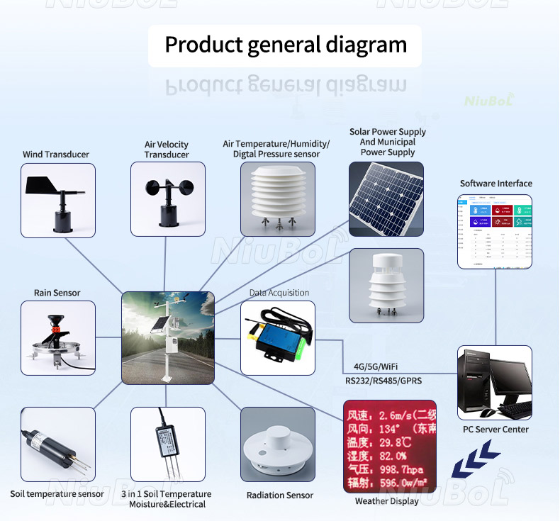
No. The package combines different sensing methods. Ultrasonic measurement supplies horizontal wind speed and direction, while other elements measure air conditions, impact-based rainfall and illuminance. Specify the seven actual parameters rather than assuming a number of acoustic paths.
Not through its Lux channel. Illuminance and solar irradiance are different quantities. Include a suitable radiation instrument and its measurement plane when PV performance or solar-resource work requires W/m2.
No. Resolution and accuracy are separate. Use each channel's accuracy expression and applicable conditions, plus the reference and comparison uncertainty. Wind accuracy expressed with a full-scale term must not be treated as a percentage of the current reading.
Compare supply, channel ranges, units, data definitions, timing and physical mounting. Verify all seven outputs after installation. Matching parameter count, housing style or RS485 connector does not establish interchangeable settings.
RS485 is the local interface. Remote delivery requires an appropriate acquisition and communications arrangement, such as a logger with a selected network connection. Specify local storage and upload behavior separately.
Provide the monitoring objective, required channel tolerances, proposed height and surrounding layout, supply and receiving equipment. Include the required rainfall record, light quantity, averaging periods and service access so NiuBoL can evaluate the compact arrangement against separate instruments.
Select this 7-in-1 ultrasonic weather sensor where its seven measured quantities, shared exposure and 12 VDC interface suit the station. Verify each channel rather than accepting serial communication alone. Send NiuBoL the channel requirements and proposed mounting arrangement to review the suitable configuration.
Sensors & Weather Stations Catalog
 Agriculture Sensors and Weather Stations Catalog-NiuBoL.pdf
Weather Stations Catalog-NiuBoL.pdf
Agriculture Sensors Catalog-NiuBoL.pdf
Water Quality Sensor Catalog-NiuBoL.pdf
Related recommendations
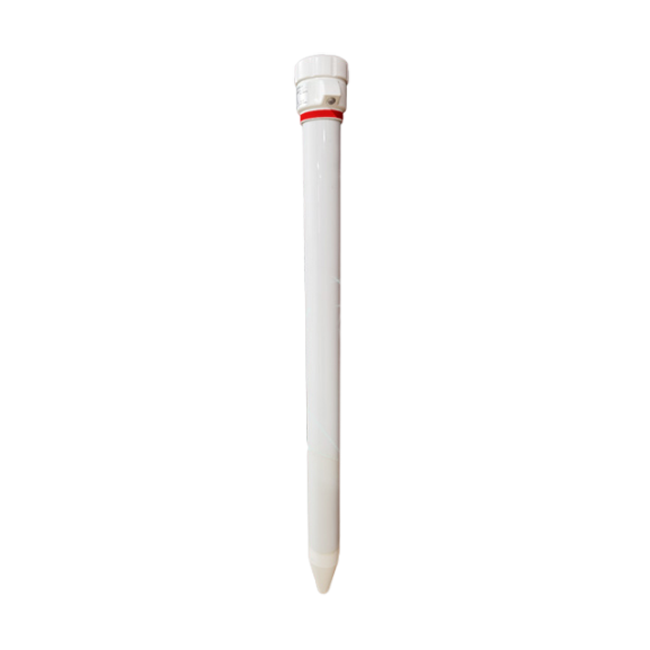 Multi-Depth Soil Sensor RS485
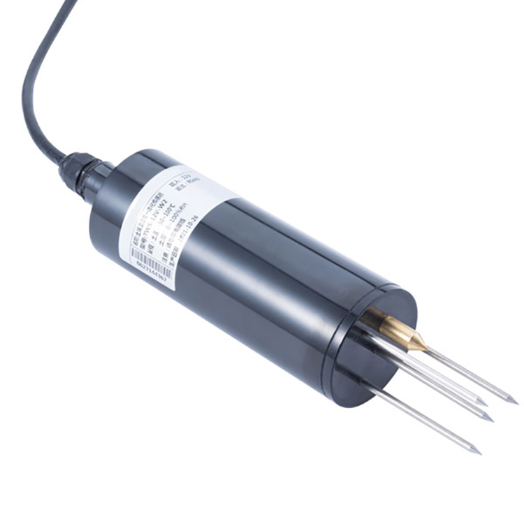 TDR Soil Moisture Sensor
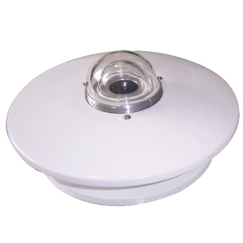 Pyranometer Solar Radiation Sensors
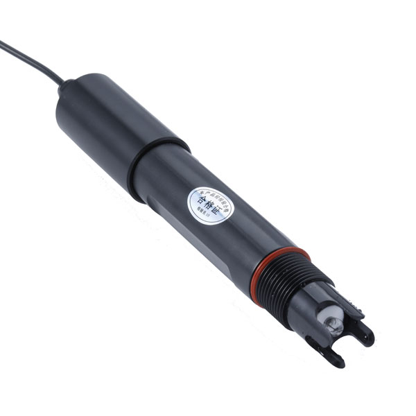 Soil ph sensor
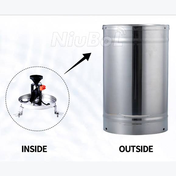 Tipping Bucket Rain Gauge
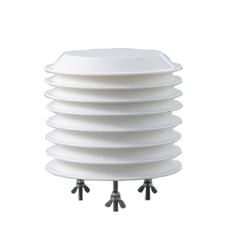 Air Temperature and Humidity Sensor


Screenshot, WhatsApp to identify the QR code
WhatsApp number:+8615367865107
(Click on WhatsApp to copy and add friends)

