





— Blogs —
—Products—
 Consumer hotline +8618073152920
WhatsApp:+8615367865107
Address:Room 102, District D, Houhu Industrial Park, Yuelu District, Changsha City, Hunan Province, China
Product knowledge
Time:2025-05-08 16:46:41 Popularity:1419
Quick Answer: Greenhouse weather station installation must separate the indoor crop environment from the outdoor weather reference. Place each sensor for the quantity it measures, then commission the complete path from instrument to logger, display and alarm. Shade an air-temperature element appropriately, but do not shade a radiation sensor or shelter a rain collector. A nearby outdoor reading cannot be assumed to represent conditions inside the greenhouse.
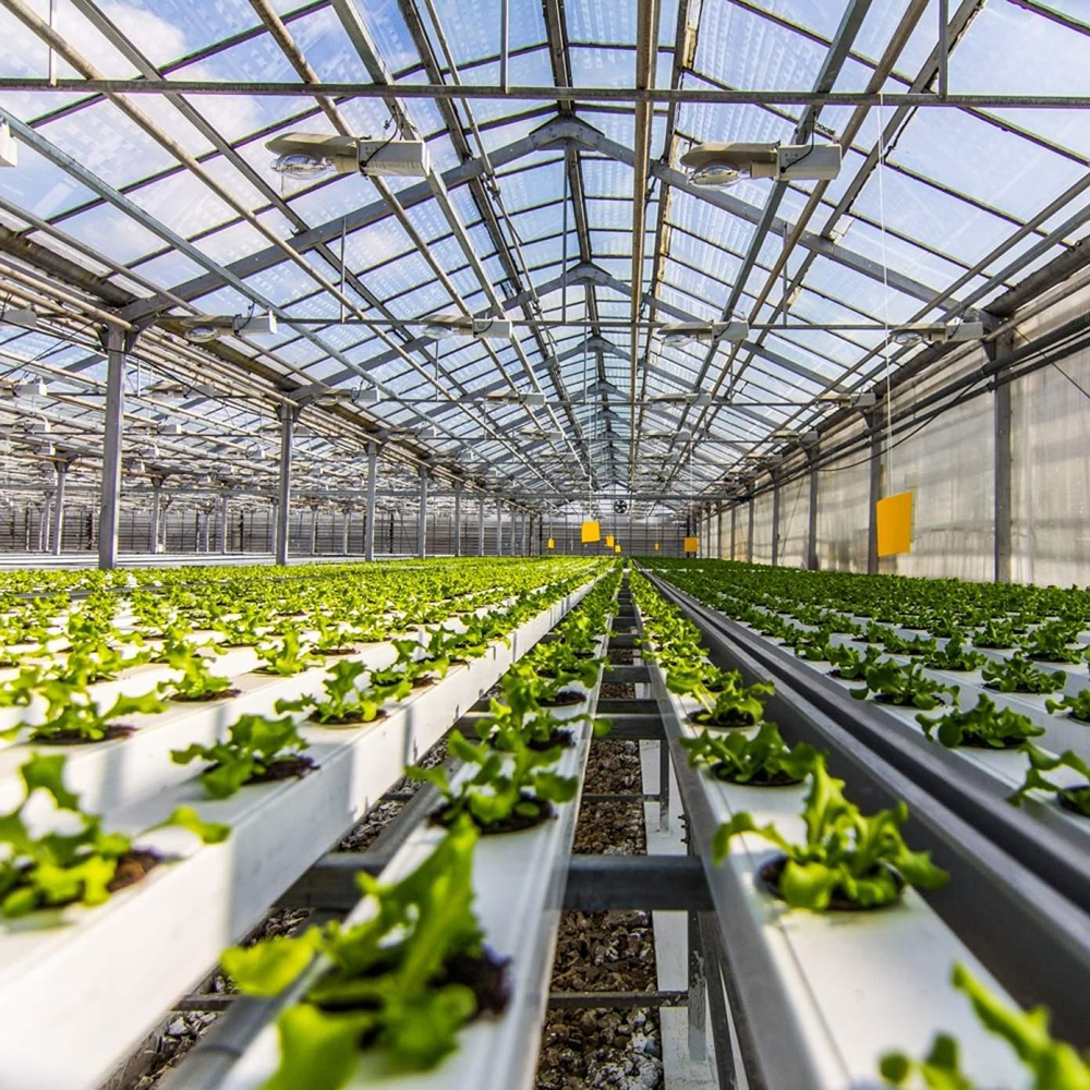
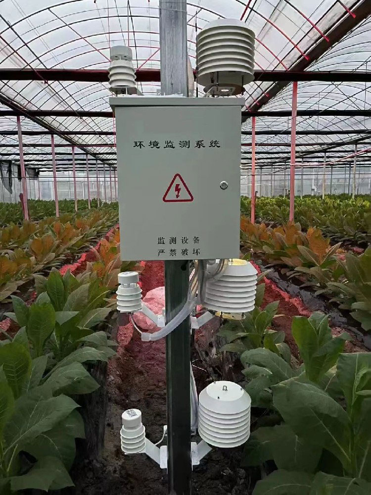
For protected crop monitoring, begin with a drawing showing crop areas, vents, doors, heaters, cooling pads, mist lines and independent irrigation zones. Give each proposed point a location label and a measurement purpose. A convenient structural post is not necessarily representative of the crop. A cabinet mounted in a central aisle may be a good acquisition location while the air sensor needs to be positioned elsewhere.
Indoor outdoor climate comparison requires distinct channels. Outdoor temperature and humidity describe the incoming air and external load; indoor measurements describe the air reaching the crop. The roof covering, ventilation, heating, irrigation and plants change those conditions. If an indoor probe cannot be installed at the intended location, redesign the mounting or sensing arrangement rather than substitute an outside value.
| Measurement | Placement objective | Avoid this installation shortcut |
|---|---|---|
| Indoor air temperature and RH | Representative crop-zone air with appropriate radiation shielding and airflow | Mounting against a heated post or directly in a mist plume |
| CO2 | Representative air in the defined growing zone | Testing immediately beside an injection outlet or an operator's breathing zone |
| Light or PAR | The specified plane and height, normally related to the canopy | Putting the sensing surface under a shield intended for temperature |
| Outdoor wind and rain | The exposure required for the external monitoring task | Assuming sheltered indoor air movement is outside wind, or placing a collector under a roof |
The greenhouse measurement recommendations published in Plant Methods distinguish crop-level observations, outside reference measurements and sensor placement. Apply that distinction to commissioning: log actual positions, shields and data-processing intervals. Research-grade comparison may also require an independent measurement set rather than relying solely on the climate controller's own inputs.
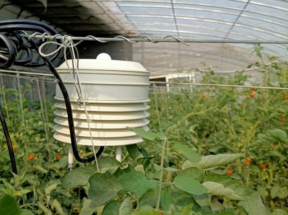
Keep air moving around a temperature and humidity shield without placing it in a concentrated fan jet unless that jet is the intended target. Avoid direct contact with leaves, wet surfaces and hot structural members. Allow the mounting height to follow crop growth where the measurement objective is canopy air. Check access for cleaning without requiring staff to pull the sensor cable.
Use a separate position when a combined head cannot satisfy all channel objectives. An appropriate air-sensing height may conflict with the required light-measuring plane. Illumination in lux is also not a substitute for PAR in umol/m2/s. Specify which quantity the crop model or operating rule uses before deciding that the integrated head meets the complete measurement requirement.
Outside, assess obstacles for the actual instrument and task. Do not apply one fixed obstacle-distance rule to every greenhouse sensor, or automatically choose the highest point. A roof-edge wind point, open-field reference and crop-level air point have different exposure goals. Keep radiation surfaces unobstructed and rain collectors open, while providing the correct enclosure protection for electronics and cable entries.
The NiuBoL NBL-W-THPLC five-parameter head is one greenhouse climate monitoring option. The figures below apply to that configuration, not every sensor in a station. In particular, its CO2 range and pressure specification should not be borrowed from a different dedicated sensor.
| Channel or interface | NBL-W-THPLC figures | Commissioning implication |
|---|---|---|
| Air temperature | -50 to +100 degrees C measuring range; +/-0.5 degrees C; 0.1 degree C resolution | The assembly's operating environment is a separate limit. |
| Air RH | 0-100% RH; +/-5% RH; 0.1% RH resolution | Range does not authorize spraying the sensing openings or connectors. |
| Pressure | 10-1100 hPa; +/-0.3 hPa; 0.1 hPa resolution | Identify actual pressure, not a dashboard value adjusted to sea level. |
| Illuminance | 0-200000 lux; +/-7%; 10 lux resolution | Use its light scaling; do not relabel the result as PAR. |
| CO2 | 0-2000 ppm; +/-(40 ppm + 2% FS); 1 ppm resolution | The full-scale term is 40 ppm on this span, not 2% of each reading. |
| Power and communication | 12 V or 24 VDC selections; RS485 / Modbus RTU; 9600 baud, eight data bits, no parity; communication interval at least 1000 ms | Confirm supply selection, stop bits and the actual point map. |
| Assembly environment | -50 to +80 degrees C; enclosure, cable jacket, joints and power consumption specified for the order | Do not assign an unsupported whole-station IP rating or infer power from voltage alone. |
If separate NBL-W-SS and NBL-W-DS instruments are included, specify their wind-sensor housings as IP65. This does not assign IP65 to every indoor sensor or cabinet. Condensation, cleaning chemicals and wet cable joints need their own assessment even when a probe has a wide measuring range.
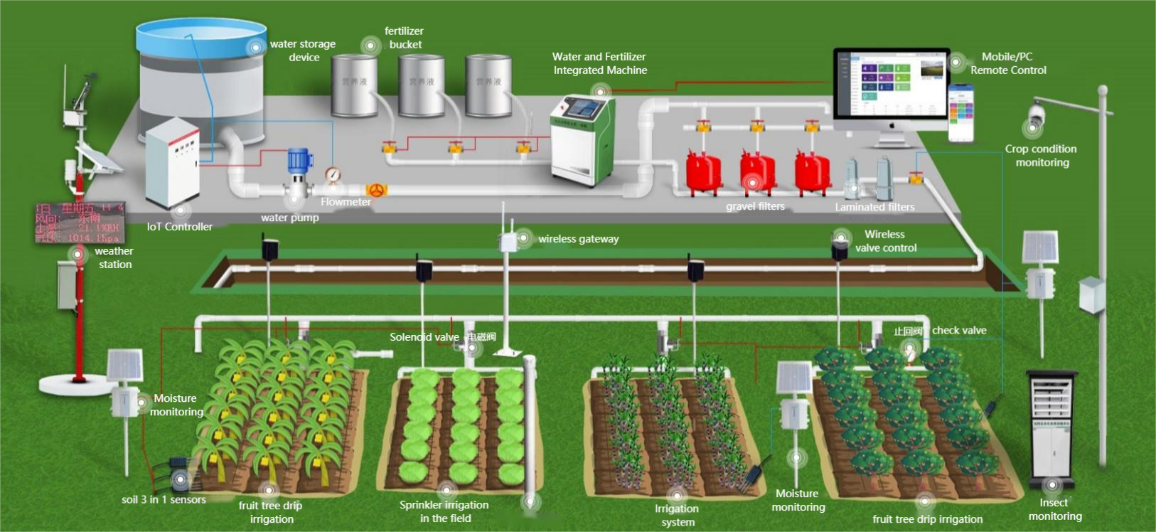
With power isolated, inspect polarity, the ordered voltage, cable identification, bus connections and secure terminations. Power one addressed instrument first and read it with the intended logger or PLC. Set additional addresses individually so duplicate devices do not produce intermittent replies. A second independent polling master on the same serial segment can create faults that resemble bad cabling.
For Modbus sensor point checks, compare the raw value, local engineering value and remote display. In the THPLC V4.0 arrangement, temperature, RH and pressure use a factor of 0.1, while the light word uses a factor of 10 and CO2 is in ppm. A valid reply can therefore produce a plausible but wrong result when one common scale is applied to every channel.
| Known illustrative word | Expected engineering value | What it tests |
|---|---|---|
| Temperature decimal 255 | 25.5 degrees C | Temperature scaling |
| RH decimal 655 | 65.5% RH | Humidity scaling and channel identity |
| Illuminance decimal 86 | 860 lux | The light channel's different scale |
| CO2 hexadecimal 0x03D4 | Decimal 980: 980 ppm | Hexadecimal conversion without importing another channel's value |
These are decoding examples, not measured greenhouse conditions. Confirm the delivered firmware and map before applying them. Keep zone names, measurement units and acquisition time visible so the technician can trace the right physical point through the system. An attractive monitoring screen is not evidence that its values belong to the labeled zone.
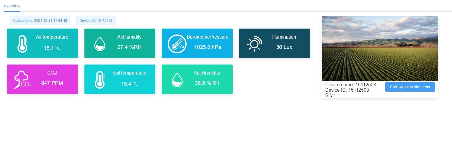
Compare an installed sensor with a suitable reference under the same stable local conditions. Place the reference close enough to observe the same air without obstructing either instrument. Allow both to equilibrate. A difference between a handheld reading at the door and a fixed sensor inside the canopy is not, by itself, a calibration error.
Distinguish verification, adjustment and functional response. A reference comparison checks agreement; adjustment changes the instrument; exposing it to a changing condition shows response. Warming a probe by hand or breathing on a CO2 sensor can demonstrate activity but cannot establish accuracy. Do not zero a CO2 channel in ordinary outside air or change a sensor calibration to conceal a decoding mistake.
Log a representative operating cycle after the point checks. Observe ventilation changes, misting or irrigation, lights and the transition between day and night as relevant. If a reading changes only when equipment starts, compare a real climate response with power disturbance, electromagnetic interference or local exhaust. The symptom should direct the inspection, not automatically trigger replacement.
| Symptom | Check first | Do not assume |
|---|---|---|
| Temperature rises when the sun reaches the post | Radiation exposure, shield airflow and thermal contact | That the whole crop zone warmed by the same amount |
| RH remains near its limit after misting | Actual condensation, direct wetting and nearby ventilation | That a measuring-range statement guarantees immediate recovery from wetting |
| Every channel drops together when a motor starts | Supply at the instrument, wiring and acquisition logs | Several simultaneous independent sensor failures |
| Local values change but the screen freezes | Upload, receiver mapping and displayed data age | That recalibrating the physical sensor will repair the display |
Use an approved test mode or simulated input where available. Verify threshold entry, persistence, clearing, recipient and acknowledgement. If a measured value commands fans, vents, heating or irrigation, test that control path separately with the equipment in a safe commissioning state. A relay indicator changing is not proof that the actuator moved in the correct direction.
Interrupt communication and power separately, then verify fault indication and recovery. Lost or stale RH must not appear as valid zero humidity, and a recovered old high-temperature record must not be presented as a new live event. Confirm any local recording, clock behavior and backfill configuration on the actual controller rather than assuming that network hardware provides them.
Before repeating the installation, record point positions, wiring, addresses, scales, reference checks, tested alarms and the working configuration. Recheck positions as the canopy grows or equipment moves. A NiuBoL inquiry can include the greenhouse drawing, indoor and outdoor point list, required quantities, existing controller and the commissioning functions required from each supplier.
An outdoor station can supply the outdoor reference. It cannot replace indoor crop-zone measurements unless a specific validated model supports that use. Install separate indoor sensors for the conditions the greenhouse controller must observe.
No. Protect electronics and appropriately shield air-sensing elements, but radiation sensors require the intended light exposure and rain collectors require open collection. Apply the installation requirement of each measurement instead of enclosing the whole station indiscriminately.
Acceptance should confirm positions, wiring, channel identity, units, scaling, reference comparisons, timing and tested faults or alarms. Include the relevant operating cycle. A successful upload alone does not establish representative measurements.
Check whether one shows an instantaneous reading and the other an average, whether timestamps match, and whether scaling was applied twice. Inspect the selected point map before adjusting calibration. Communication success does not prove numerical interpretation.
No. Confirm the quantities, ranges and suitable position of the selected head. THPLC measures illuminance rather than PAR and has a 0-2000 ppm CO2 span. Soil, leaf wetness, external wind and rain are separate measurements where required.
The responsible control and equipment team should commission the approved logic and physical outputs. Sensor supply does not automatically include motor protection, actuator feedback or a complete climate-control program. Define those responsibilities before installation.
Greenhouse weather station installation succeeds when the measured place, physical quantity and receiving channel agree. Separate indoor from outdoor observations, preserve the exposure each instrument needs and verify the full data path before adjusting sensors. NiuBoL equipment can then be selected and commissioned against an explicit point list rather than a generic station package.
Prev:Greenhouse Weather Station Software: Verify Access and Historical Export
Next:Greenhouse Weather Station Commissioning: Trace Each Measurement Point
Related recommendations
Sensors & Weather Stations Catalog
 Agriculture Sensors and Weather Stations Catalog-NiuBoL.pdf
Weather Stations Catalog-NiuBoL.pdf
Agriculture Sensors Catalog-NiuBoL.pdf
Water Quality Sensor Catalog-NiuBoL.pdf
Related products
 Combined air temperature and relative humidity sensor
 TDR Soil Moisture & Temperature Sensor for irrigation| RS485 |4-20mA| NBL-S-THR
 Soil pH sensor RS485 soil Testing instrument soil ph meter for agriculture |NBL-S-PH
 Wind Speed sensor Output Modbus/RS485/Analog/0-5V/4-20mA
 Tipping bucket rain gauge for weather monitoring auto rainfall sensor RS485/Outdoor/stainless steel
 Pyranometer Solar Radiation Sensor 4-20mA/RS485


Screenshot, WhatsApp to identify the QR code
WhatsApp number:+8615367865107
(Click on WhatsApp to copy and add friends)

