





— Download —
 Consumer hotline +8618073152920
WhatsApp:+8615367865107
Address:Room 102, District D, Houhu Industrial Park, Yuelu District, Changsha City, Hunan Province, China
All products

Select a NiuBoL 2-in-1 ultrasonic wind sensor for RS485 station retrofits. Check airflow, direction alignment and logger compatibility before requesting a quotation.
Tel/WhatsApp:+8615367865107
Email:Arvin@niubol.com +Nearly 100 partner companies in more than 75 countries. We are committed to providing high-quality, practical products to meet your needs and help you solve problems. Our products comply with international standards and are certified with ISO, CE and RoHS.Product Details
Quick Answer: This NiuBoL 2-in-1 ultrasonic wind speed and direction sensor supplies both horizontal wind channels through RS485 Modbus. It covers 0-40 m/s and 0-360 degrees, uses 12 VDC and has an IP65 housing. Choose it when the receiving logger can read the digital output and the installation provides clear airflow. Replacing cups and a vane removes their bearings, but does not remove exposure, orientation or data-processing requirements.
A mechanical station may have one frequency input for wind speed and a separate analog input for the vane. This ultrasonic unit instead sends the two measurements over RS485. A matching plug or mast diameter does not make it an electrical replacement: the logger needs a compatible Modbus master or an appropriate acquisition interface.
| Existing requirement | What the replacement must provide |
|---|---|
| PLC expects wind-speed pulses | A frequency input cannot read RS485 directly. Review a compatible digital input path or select a different instrument with the required native output. |
| Logger already reads Modbus instruments | Check serial settings, available addresses and the delivered wind register definitions; do not copy a temperature sensor's scaling. |
| Control depends on gusts or short peaks | Verify the available wind statistics and acquisition timing before replacement. An occasional instantaneous sample does not establish a gust measurement. |
| Research requires vertical wind | This two-channel horizontal instrument is not a three-dimensional wind system. Specify the required velocity components and data rate separately. |
| Parameter | Specification |
|---|---|
| Measured channels | Horizontal wind speed and wind direction |
| Wind speed | 0-40 m/s; 0.01 m/s resolution |
| Wind direction | 0-360 degrees; 1 degree resolution |
| Specified accuracy bands | Low wind: +/-0.5 m/s and +/-3 degrees. High wind: +/-1 m/s and +/-5 degrees. Include the applicable band boundaries in the order-specific performance requirements. |
| Supply and power | 12 VDC; 0.2 W |
| Digital output | RS485; Modbus; 9600 baud |
| Operating environment | -40 to 70 degrees C; 0-100% RH |
| Storage temperature | -50 to 80 degrees C |
| Housing and protection | Engineering plastic; IP65 |
| Dimensions and weight | 90 mm diameter x 140 mm; 0.6 kg |
The 0.01 m/s output increment is not the speed accuracy. Likewise, IP65 describes the sensor housing, not the entire installed cable route or immunity to lightning. Specify outdoor joints, enclosure entries and surge protection for the actual site.
Install in open airflow, above or away from wakes created by buildings, trees, poles, solar panels and the mast itself. The appropriate height depends on the application standard. Keep the sensor level, use a rigid vertical pipe and route the cable inside or along the mast without obstructing the acoustic path.
A mast beside a building can receive disturbed flow even when the sensor communicates normally. Changing construction, crop height or a nearby panel installation can also change the exposure over time. Keep a drawing or photographs of surrounding obstacles so a persistent shift in wind behavior can be investigated without immediately assuming sensor drift.
A rigid installation matters for direction as well as signal reliability. Check mast plumb, support movement and cable clearance before accepting the point. Do not extend a boom or alter the mount without reviewing structural loading and the resulting measurement location.
Keep this anemometer more than 2 m from a radar scanning plane. Use that as a model-specific installation requirement, not a universal guarantee of electromagnetic compatibility. Review the actual radio equipment, motors, vibration sources and project separation rules at ports, bridges and industrial sites.
Orient this instrument's pointing mark toward north. Establish geographic direction using an appropriate method and account for magnetic declination or nearby magnetic interference when using a compass. Verify the receiving system's direction convention rather than treating the mark alone as acceptance.
If the display has a consistent angular offset, inspect the physical reference and the logger configuration first. A software correction can be applied twice when a later technician realigns or replaces the instrument. Record any intentional correction with the installation orientation so a spare can be fitted without changing the meaning of the channel.
Direction crosses the 0/360-degree boundary. A change from 350 to 10 degrees crosses north by 20 degrees, not by 340 degrees in the opposite direction. Use the required circular or vector processing for directional statistics. At very low wind, direction may be unstable; apply the instrument's quality information and the project's calm-wind treatment rather than presenting every number as a meaningful prevailing direction.
Confirm the delivered protocol revision, address, serial format and wind units with one sensor connected locally. Read speed and direction as separate channels. A valid serial response proves communication, not correct orientation, scaling or sampling. Save the working configuration before adding other devices to the installed bus.
Provide stable 12 VDC at the sensor after cable loss. Use a bus topology, unique addresses and documented baud rate, parity, register type and scaling. Termination belongs at the network ends where required. A gateway can forward data remotely, but the local logger should manage polling and storage.
In a replacement project, compare the new and old instruments over a useful overlap period when practical. Document differences in height, mounting and averaging so they are not confused with an instrument error. A cup rotor, vane and ultrasonic instrument can respond differently to the same changing wind; a brief hand-held comparison is not a complete field calibration.
A compatible data logger or gateway provides onward transmission when required. Agree which device calculates averages and maximum values and which timestamp accompanies the record. Use the acquisition system to identify a stale or failed channel instead of replacing missing data with calm wind.
| Acceptance task | Useful comparison |
|---|---|
| Speed response | Compare with a suitable reference under reasonably comparable exposure and averaging. Investigate mounting or timing differences before adjusting scale. |
| Direction reference | Check the physical mark, geographic reference and displayed convention. Retain the agreed offset, if any. |
| Time-dependent output | Compare the required instantaneous, average or maximum statistic using matching intervals at the sensor, logger and platform. |
| Communication recovery | Interrupt the bus or receiving process safely. Verify missing-data indication and recovery without confusing the interruption with zero wind. |
For an agricultural station, the recorded wind can inform work planning under the operator's rules, provided the point remains representative as the crop changes. At a road, bridge or coastal site, survey structure wakes and radio exposure before accepting a convenient mounting location. A general meteorological channel is not automatically an approved safety shutdown detector.
Ultrasonic transit-time measurement avoids cup bearings and vane pivots. That reduces wear and starting-friction problems, which is useful at remote stations. It does not make siting irrelevant or eliminate every inspection. Ice, contamination, nearby structures and electromagnetic interference can still affect availability or representativeness.
Include cleaning access in the layout and inspect the measurement path after contamination or icing. An operating-temperature range does not establish that ice cannot obstruct the instrument. If heating or another severe-weather arrangement is required, confirm an actual suitable configuration and its power demand before ordering.
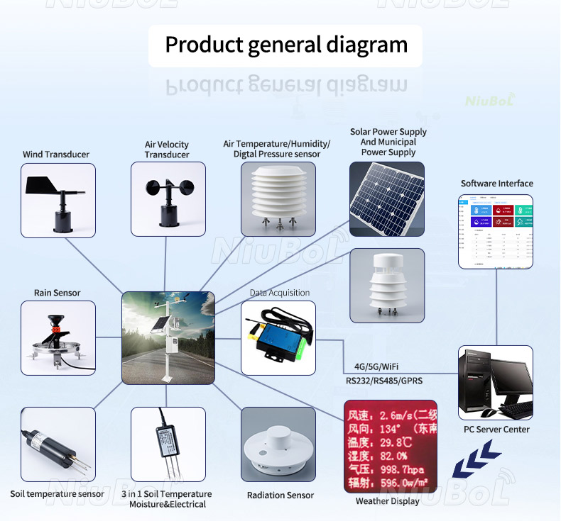
The modular station diagram below shows separate cups and a vane. It illustrates the station-level mounting and acquisition context, not the contents of an ultrasonic sensor package. When changing that station to ultrasonic wind measurement, review the wind input and mount rather than assuming that every illustrated component changes with the sensor.

Only if the existing logger can read the required RS485 Modbus output and map both wind channels. A logger with only pulse and analog inputs needs a different acquisition arrangement or a different sensor output. Check this before ordering a mechanical replacement.
Do not infer that from the wind-speed range. Specify the gust calculation method, required observation rate and reporting interval, then confirm whether the sensor provides that statistic or the logger must calculate it from suitable samples.
Check installation orientation and existing software corrections first. Establish the geographic reference and receiving convention, then document any deliberate correction. Repeating the same unexplained offset in several software layers makes later maintenance unreliable.
It has no cup bearings or vane pivot to service, but the measurement path, support, connectors and cable still need inspection. Dust, ice, damage or a changed obstruction can affect data without producing an obvious communication failure.
Send the required speed range and statistics, mast drawing, cable route, supply and receiving logger or PLC. Include the site environment, radio or radar exposure and any shutdown function. These determine whether this digital wind configuration fits the duty.
Choose this 2-in-1 ultrasonic wind sensor for compatible digital acquisition of horizontal speed and direction. Check the logger interface, exposure, reference orientation and required statistics before treating it as a replacement for a mechanical set. NiuBoL can review those details against the proposed station configuration.
Sensors & Weather Stations Catalog
 Agriculture Sensors and Weather Stations Catalog-NiuBoL.pdf
Weather Stations Catalog-NiuBoL.pdf
Agriculture Sensors Catalog-NiuBoL.pdf
Water Quality Sensor Catalog-NiuBoL.pdf
Related recommendations
 Multi-Depth Soil Sensor RS485
 TDR Soil Moisture Sensor
 Pyranometer Solar Radiation Sensors
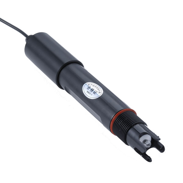 Soil ph sensor
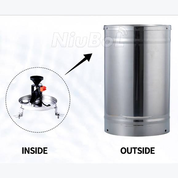 Tipping Bucket Rain Gauge
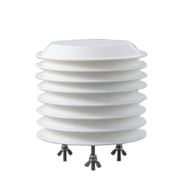 Air Temperature and Humidity Sensor


Screenshot, WhatsApp to identify the QR code
WhatsApp number:+8615367865107
(Click on WhatsApp to copy and add friends)

