





— Download —
 Consumer hotline +8618073152920
WhatsApp:+8615367865107
Address:Room 102, District D, Houhu Industrial Park, Yuelu District, Changsha City, Hunan Province, China
All products

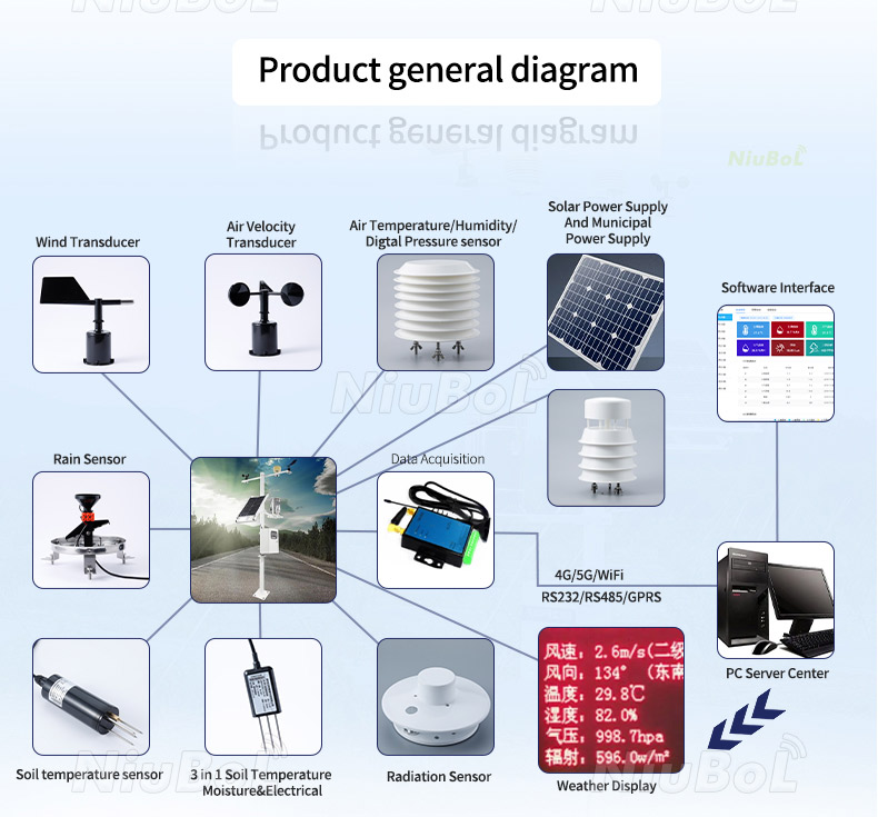
Use the NiuBoL soil salinity and EC sensor for root-zone salt monitoring. Check soil contact, irrigation trends and output scaling before requesting a project quote.
Tel/WhatsApp:+8615367865107
Email:Arvin@niubol.com +Nearly 100 partner companies in more than 75 countries. We are committed to providing high-quality, practical products to meet your needs and help you solve problems. Our products comply with international standards and are certified with ISO, CE and RoHS.Product Details
Quick Answer: The NiuBoL NBL-S-SC soil salinity and EC sensor provides salinity indication over 0-8000 mg/L and electrical conductivity over 0-15 mS/cm. RS485 Modbus, 4-20mA and 0-5V versions support different acquisition systems. Select it for salt-condition trends at defined soil locations, with moisture and irrigation context. Neither channel identifies individual ions or directly establishes the mass of salt stored in an entire root zone.

| Item | NBL-S-SC specification |
|---|---|
| Salinity indication | 0-8000 mg/L; 1 mg/L resolution; +/-5% accuracy |
| Electrical conductivity | 0-15 mS/cm; 0.01 mS/cm resolution; +/-5% accuracy |
| Supply | 12-24 VDC |
| Output versions | RS485 Modbus RTU, 4-20mA or 0-5V, as ordered |
| Sensing element | Ceramic technology for direct soil installation |
| Operating environment | -10 to 60 degrees C; 0-95% RH |
| Transmitter housing | Waterproof plastic housing; confirm the ordered probe and transmitter arrangement |
Confirm the accuracy reference basis and checking method with the selected configuration before setting acceptance tolerances. Display increments of 1 mg/L and 0.01 mS/cm do not establish errors of those sizes. Keep the probe, transmitter, cable and receiving input identified as one measurement arrangement.
The humidity interval is an environmental specification, not a protection rating for buried cable joints. Identify which parts of the ordered assembly are intended for soil contact and how the transmitter and connections will be protected. Do not assign another probe model's IP rating to this installation.
Electrical conductivity responds to the ions present in soil water, while the salinity channel reports the sensor's corresponding dissolved-salt indication. Neither value identifies which salts are present. For agronomic decisions, combine the trend with irrigation-water analysis, soil sampling and the tolerance of the actual crop and growth stage. A universal EC threshold copied from another crop or substrate can lead to the wrong irrigation response.
Salinity in mg/L is a concentration indication on the instrument's calibration basis. It is not mg/kg of dry soil, and it is not a mass-per-area inventory. Calculating salt stored in a root zone requires an appropriate sampling and accounting method; changing the unit label cannot supply the missing soil and water information.
Likewise, equal conductivity does not establish equal sodium, chloride or nutrient composition. Different ions contribute differently to electrical conduction. Use chemical analysis when the identity of an ion affects the agronomic or engineering decision, rather than treating two sensor outputs as two independent laboratory assays.
Keep field probe readings separate from laboratory extract results. An extract method changes the sample preparation and water ratio. Matching conductivity units does not establish that a crop limit developed for one method can be applied directly to another.
After irrigation, EC can fall at one depth because salts are diluted or moved downward, then rise again as water is taken up or evaporates. Review moisture, EC and event timing together. A single reading taken immediately after installation or watering is not an acceptance result; allow the probe-soil system to settle and establish a site baseline.
A lower root-zone reading does not, by itself, establish that salt has left the managed profile. Compare the event with an appropriately positioned lower point and drainage observations when leaching is the question.
A deeper point that rises after irrigation may indicate redistribution into that layer. It does not quantify the transported salt mass without an appropriate flow and concentration assessment. Review the sequence across depths rather than using one low value as proof that a leaching operation succeeded.
For repeated events, compare similar stages of the irrigation cycle and retain the water source and fertilizer history. A change in irrigation-water composition can affect the trend even when the irrigation volume and controller settings have not changed. Temperature and moisture conditions also belong with the comparison.
Where soil becomes very dry, weak or interrupted conductive pathways can limit interpretation. Inspect moisture and contact before diagnosing a low EC value as low salinity. Do not wet an isolated sensor pocket merely to obtain a more convenient value and then present it as an undisturbed field observation.
Choose a depth that represents the managed root zone and a horizontal position that reflects the irrigation pattern. A probe immediately beside a drip emitter can report a wet, recently flushed pocket; one outside the wetted bulb can report a much drier and more concentrated condition. Multi-depth monitoring is preferable where salts are expected to move below the active roots.
The ceramic sensing area must contact undisturbed or firmly repacked soil. Air gaps, stones and loose backfill interrupt the electrical path and make readings difficult to compare. For a profile installation, open the face, make a close-fitting horizontal hole, insert the probe and restore the original layer order. For drilling, lower the probe to the target depth and compact the return soil in stages.
Route the cable so it does not create a preferential path for surface water directly to the sensing point. Protect the transition to exposed cable and keep connectors accessible where the design permits. A cable channel carrying irrigation water can make the sensor follow the installation disturbance rather than the surrounding soil.
Record depth and horizontal distance from emitters, drains or treatment boundaries. Use paired positions only when their difference answers a question, such as the edge of a wetted region versus a managed root-zone point. An average of unrelated positions can conceal the very salt distribution the project needs to investigate.
A single analog input carries one scalar value at a time. Confirm whether each physical output represents salinity or EC, and whether both required quantities are available through the ordered arrangement. A product offering both measurement functions does not automatically include two simultaneous current loops.
| Ordered channel | 4-20mA conversion | Value at 12 mA |
|---|---|---|
| Salinity, 0-8000 mg/L | S = (I - 4) / 16 x 8000 | 4000 mg/L |
| EC, 0-15 mS/cm | E = (I - 4) / 16 x 15 | 7.5 mS/cm |
Here I is current in mA. For the corresponding 0-5V version, divide measured volts by five and multiply by the selected channel's full scale. The same electrical midpoint therefore has different engineering meanings on the two channels. These are scaling examples, not simultaneous soil observations or a salinity-to-EC conversion factor.
Check the input and its conversion with an appropriate electrical test before judging the installed soil response. A correct PLC midpoint confirms part of the acquisition path; it does not check soil contact or calibration. If the current channel is unavailable, identify that condition instead of substituting a genuine zero.
The NBL-S-SC RS485 configuration uses Modbus RTU at 9600 baud, 8 data bits and no parity, with at least 1000 ms between communications. Match the delivered stop-bit setting and device address before connecting multiple points.
The two-value data definition places salinity first, in mg/L, followed by EC with a 0.01 mS/cm conversion. Verify that definition against the delivered configuration. Do not apply a common multiplier to both values or exchange their names because both change during an irrigation event.
Follow one identified observation from local acquisition to the exported record. Confirm both units, decimal positions and timestamps. If a remote system also calculates another salt indicator, keep it separate from the native sensor values and identify its calculation basis.
After installation, allow the disturbed soil and sensing region to reach a representative condition. Judge the baseline with moisture and event information rather than a fixed number of hours assumed for every soil. Record stabilization observations and any rejected data instead of silently treating the first valid serial reply as acceptance.
Use a compatible reference and a supplier-agreed calibration procedure when checking or correcting the instrument. Keep the reference solution, temperature basis and applicable range with the result. An arbitrary field point or an unrelated handheld reading is not enough to justify a new conversion coefficient.
If a point changes after excavation, cable repair or probe replacement, investigate the physical work as well as the electronics. Restoring the same channel name does not restore the previous soil contact or sensing location. Retain the intervention date so a change in installation is not misread as a treatment effect.
For a quotation, identify the soil and management question, expected range, depths and lateral positions, output quantities and receiver. Include the actual probe/transmitter layout, cable routing and joint protection. A logger or gateway can carry the records onward, but it cannot correct an unrepresentative buried point.
No. It is a concentration indication at the sensing point on the instrument's calibration basis. Soil salt inventory requires an appropriate sampling and accounting method, and mg/L cannot simply be relabeled as mg/kg of dry soil.
No. Dilution, redistribution and changing contact can also lower the local reading. Review moisture, deeper observations and drainage information before concluding that salt has left the managed root zone.
No. Electrical conductivity combines the contribution of dissolved ions. Use appropriate chemical analysis when ion identity or a specific nutrient determines the decision.
Do not assume so. Specify which quantity each physical output must carry and confirm the supplied channel arrangement. A single 4-20mA signal cannot communicate two independent continuous values without an additional defined scheme.
After electrical and unit checks, verify firm contact and a representative baseline under known soil conditions. Use a defined comparison and observe relevant moisture or irrigation changes. No universal settling period applies to every disturbed soil and installation.
Not by itself. Soil conductivity can be an environmental input to a corrosion investigation, but coating, protection systems and the required corrosion measurements need their own engineering assessment. Do not relabel the soil channel as a corrosion-rate instrument.
Provide the medium, salt-monitoring objective, ranges, installation positions, required analog or digital quantities and receiving equipment. Include cable and transmitter arrangement, protection of connections and the intended reference method so NiuBoL can assess the complete measurement point.
Use the soil salinity and EC sensor to investigate salt-condition changes at defined positions. Interpret its outputs with moisture and irrigation context, specify each acquisition channel and verify contact before accepting a trend. Send NiuBoL the soil profile and required output quantities to review an appropriate arrangement.
Prev:Soil heat flux sensor Heat flow measurement instrument for measuring the heat flux inside the soil
Next:illumination sensor detection lighting intensity Lux for Greenhouse agriculture IOT
Sensors & Weather Stations Catalog
 Agriculture Sensors and Weather Stations Catalog-NiuBoL.pdf
Weather Stations Catalog-NiuBoL.pdf
Agriculture Sensors Catalog-NiuBoL.pdf
Water Quality Sensor Catalog-NiuBoL.pdf
Related recommendations
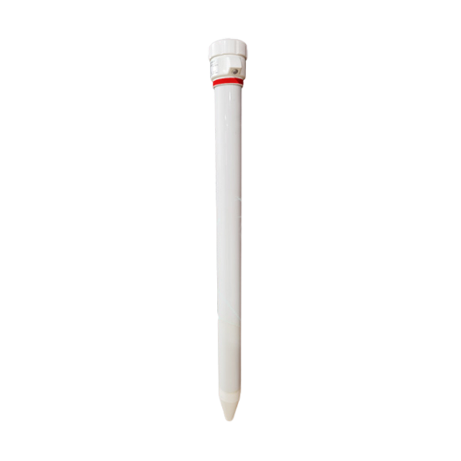 Multi-Depth Soil Sensor RS485
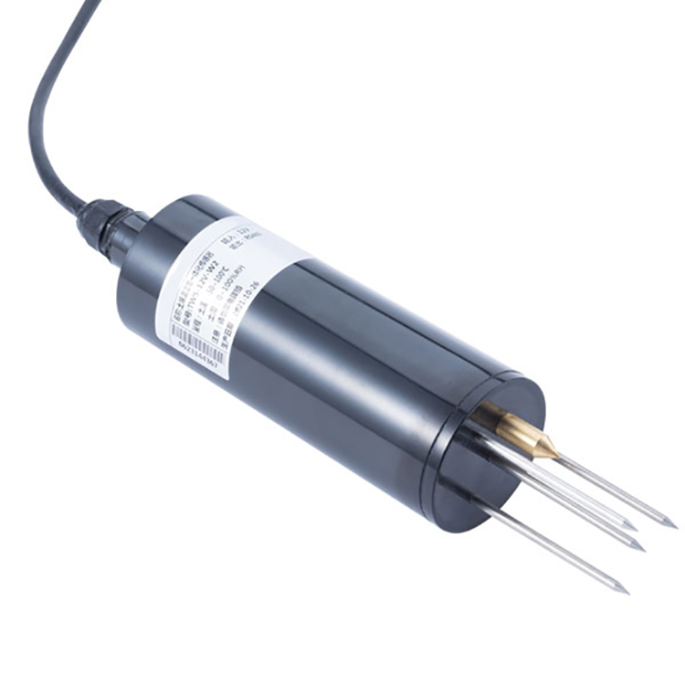 TDR Soil Moisture Sensor
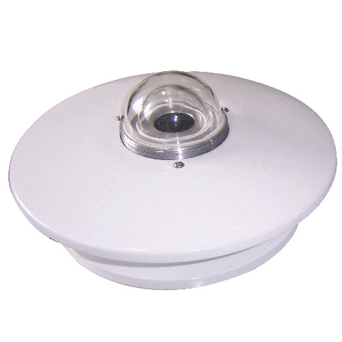 Pyranometer Solar Radiation Sensors
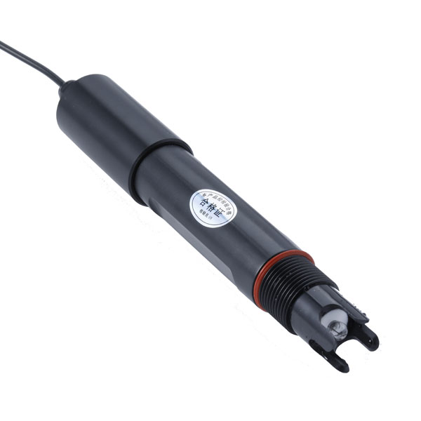 Soil ph sensor
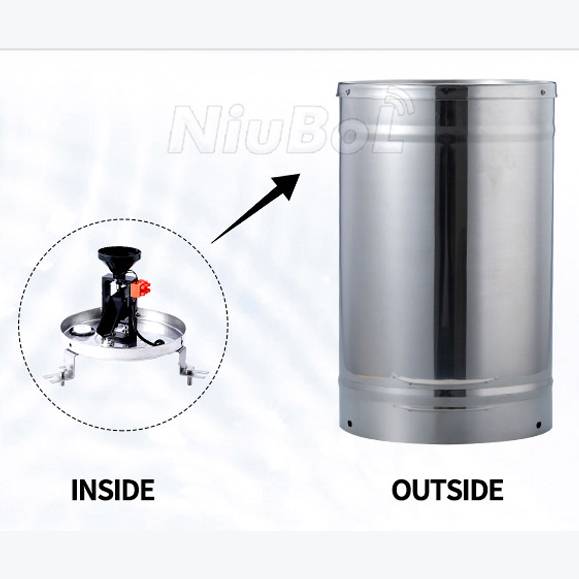 Tipping Bucket Rain Gauge
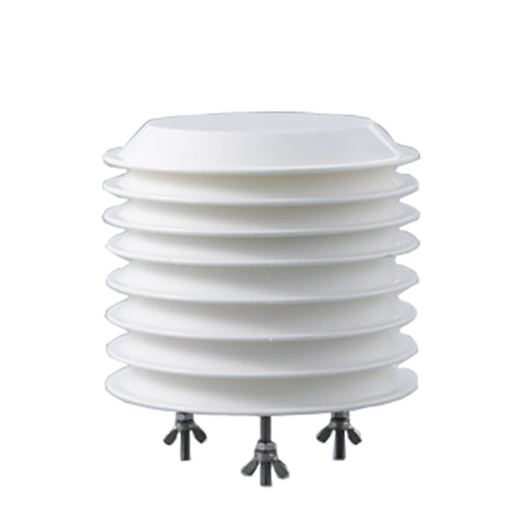 Air Temperature and Humidity Sensor


Screenshot, WhatsApp to identify the QR code
WhatsApp number:+8615367865107
(Click on WhatsApp to copy and add friends)

