





— Download —
 Consumer hotline +8618073152920
WhatsApp:+8615367865107
Address:Room 102, District D, Houhu Industrial Park, Yuelu District, Changsha City, Hunan Province, China
All products

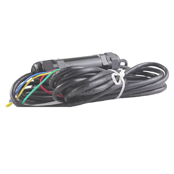
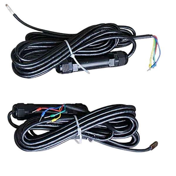
Install a NiuBoL solar panel temperature sensor with repeatable backsheet contact and supported cable. Check output scaling and diagnose loose bonds before handover.
Tel/WhatsApp:+8615367865107
Email:Arvin@niubol.com +Nearly 100 partner companies in more than 75 countries. We are committed to providing high-quality, practical products to meet your needs and help you solve problems. Our products comply with international standards and are certified with ISO, CE and RoHS.Product Details
Quick Answer: A solar panel temperature sensor is bonded to the PV module backsheet to measure surface temperature for performance analysis. This contact sensor covers -50 to 100 degrees C with +/-0.5 degrees C stated accuracy and selectable 4-20mA, voltage or RS485 output. Repeatable mounting position, thermal contact and cable strain relief matter as much as the transmitter specification.
| Item | Specification |
|---|---|
| Range | -50 to 100 degrees C; optional -20 to 50 degrees C |
| Accuracy | +/-0.5 degrees C |
| Supply | 5, 12 or 24 VDC |
| Outputs | 4-20mA, 0-2.5V, 0-5V or RS485 |
| Cable | 5 m |
| Load | Voltage output: at least 1 kohm; current output: up to 250 ohm |
| Operating conditions | -50 to 100 degrees C; 0-100% RH |
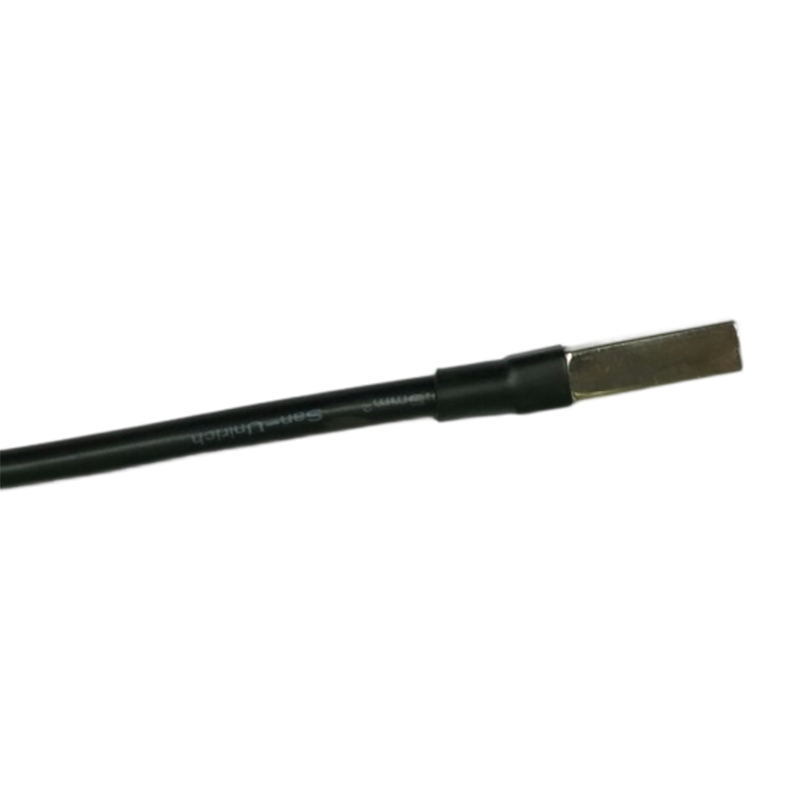
| Probe weight | 125 g |
| Power | 0.15 W |
The probe measures the local backsheet surface where it is bonded. It is not ambient air temperature, cell-junction temperature or a thermal image of the full module. The reading is valuable when compared with irradiance, ambient temperature, wind and electrical output, provided all monitored modules use the same installation method.
For backsheet monitoring, position the contact probe near the center of the module rear surface where the module design permits. Check that location against the module manufacturer's restrictions and the monitoring method before bonding. A frame position, junction-box position and central backsheet position can have different thermal behavior. Do not change the location simply to shorten a cable without considering what the temperature record should represent.
Use the same relative location for modules being compared. On a plant with different module types, mounting structures or orientations, select representative groups rather than choosing a universal sensor count from plant capacity. Establish the plant-wide measurement layout before crews begin repeating the bonding procedure across the array.
Choose the documented rear-surface position, normally away from the frame, junction box and obvious local shade unless the project standard states otherwise. Clean and dry the approximately 22 x 12 mm contact area. Apply the supplied thermally conductive silicone evenly and avoid trapped air between probe and backsheet.
Keep the module surface dry and use a cleaning and bonding method acceptable to the module manufacturer. A thick, uneven or partly detached bond introduces a different heat-transfer path from a thin, consistent contact. Adding more adhesive is not automatically a cure for a poor fit.
Hold the probe in place for about 5-10 minutes after application. This initial fixing period is not a universal adhesive cure time. Temperature, surface condition and the bonding product's own instructions determine when the cable can be loaded and the installation returned to normal service.
Place the probe immediately after applying the compound and hold it for about 5-10 minutes as instructed. The cable must then be secured along the module support so connector movement, wind and maintenance work do not pull on the sensing element. Use UV- and temperature-suitable fasteners selected for the site.
Allow for module movement and maintenance access, and for tracker movement where applicable. Check the route through the full allowed travel without putting tension on the sensing pad. Keep the cable clear of sharp edges and avoid creating a loop that can be caught during cleaning.
The standard cable length is 5 m. Specify the required total length and selected output before ordering. An extension has different consequences for voltage, current and RS485 versions; it also introduces a joint that must survive the installation environment. Do not splice an outdoor cable and assume the probe's temperature rating describes the new connector or junction.
For bifacial modules, check the probe, adhesive and cable arrangement for rear-side shading and compatibility with the module design. Approval of a backsheet mounting method on one module construction does not automatically apply to a different rear-glass construction.
For 4-20mA, confirm loop supply, receiving resistance and scaling. For voltage output, verify the input impedance and common reference. For RS485, set the correct address and serial parameters and use the ordered register map. Check temperature at the logger, supervisory display and exported record, not only at one interface.
For a linear 4-20mA version spanning -50 to 100 degrees C, temperature is -50 + (I - 4) / 16 x 150. The midpoint, 12 mA, is 25 degrees C. For the optional -20 to 50 degrees C span, 12 mA instead corresponds to 15 degrees C. Use the span on the actual order and wiring documents; a generic temperature-input template can create a plausible but wrong result.
Voltage-output versions similarly need the correct full-scale voltage and receiving impedance. The RS485 option requires its delivered register definitions and serial settings, not the analog formula. Check the value through the complete receiving path, including any conversion in a gateway, before comparing it with plant performance data.
First inspect and identify the physical point: module row, module ID, rear-surface position, bonding material and supported cable route. Next verify the electrical scale using the method appropriate to the selected output. Finally compare the installed temperature with a suitable contact reference under conditions stable enough for the comparison method.
A nearby reference needs comparable thermal contact and a defined position. An infrared reading introduces surface-emissivity and viewing considerations; do not interpret a difference between methods as a transmitter offset without investigating those conditions. Comparing two sensors on different parts of the module can also test the temperature gradient rather than their calibration.
Log irradiance, ambient temperature and module temperature on compatible time intervals where those channels are available. A warm module under strong sunlight is expected behavior, not proof of a defect. Look for persistent differences between comparable modules or a change in the relationship after installation work.
| Temperature behavior | What to inspect before changing calibration |
|---|---|
| Reading moves toward ambient after cable work | Inspect for partial detachment and cable tension. An unbonded probe can remain electrically healthy while measuring the wrong thermal condition. |
| Stable offset from a neighboring module | Compare mounting position, module construction, shading and rear ventilation, then compare the electrical scaling. |
| Step change after a replacement | Check sensor span, output, channel assignment and the new bonding method. Mark the intervention in the operating record. |
| Intermittent or frozen result | Inspect supply, connections and the receiving channel. Do not assume every flat trend is a detached probe. |
Agree the removal and cleaning method before attempting a repair. Scraping a rear surface or using an unsuitable solvent can damage the module. Follow the module and adhesive requirements and inspect the sensor and cable before deciding whether the existing probe can be reused.
Rebond at the documented location where permitted, restore strain relief and repeat the acceptance comparison. If the position or contact method changes, record that change; continuity of the logger tag does not make the new physical measurement identical to the old one.
At rooftop sites, plan access and the cable repair route before installation. At a test facility, repeat the same bonding method across test articles so the attachment does not dominate the comparison. For a utility plant, retain a labeled installation photograph so later field teams can locate the right probe rather than disconnect a neighboring module's channel.
No. It measures local rear-surface temperature at the bond. Any use as an input to a cell-temperature or power model needs the assumptions of that model and a repeatable mounting method. It does not replace a thermal inspection for locating individual hot spots.
Not necessarily. Five to ten minutes is an initial fixing period, not a general full-cure specification for every adhesive and weather condition. Follow the bonding material and module requirements, then secure the cable so it does not load the sensing pad.
A central rear-surface point is a starting location; module restrictions and the project's measurement method take precedence. Use a documented, consistent relative position for comparable modules and explain any necessary exception rather than mixing positions without a record.
Review the actual rear surface, permitted adhesive, electrical safety requirements and shading from the probe and cable. Do not assume that instructions for a polymer backsheet transfer unchanged to rear glass. Confirm the approved attachment with the module requirements before installation.
Send the existing temperature span, output, supply, cable length, connector and logger details, together with the module and bonding method. A replacement with a different span can display a believable temperature while invalidating the existing conversion.
Use a logger or PLC input compatible with the ordered current, voltage or RS485 output, then verify the onward tag, units and timestamp. A logger or gateway handles remote transfer when required. Agree whether it transmits instantaneous samples or interval statistics so temperature can be compared with irradiance and inverter records.
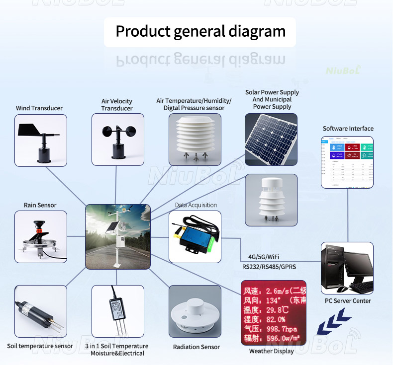
A useful PV backsheet temperature channel needs a repeatable bond, supported cable and correct logger conversion. Check those three items before interpreting an offset as module degradation or sensor drift. For installation or replacement inquiries, send NiuBoL the module construction and existing output and acquisition details so the supplied version matches the site.
Prev:How much Automatic direct radiation Sensor Pyranometer for Photovoltaic Sun Solar Tracking System
Sensors & Weather Stations Catalog
 Agriculture Sensors and Weather Stations Catalog-NiuBoL.pdf
Weather Stations Catalog-NiuBoL.pdf
Agriculture Sensors Catalog-NiuBoL.pdf
Water Quality Sensor Catalog-NiuBoL.pdf
Related recommendations
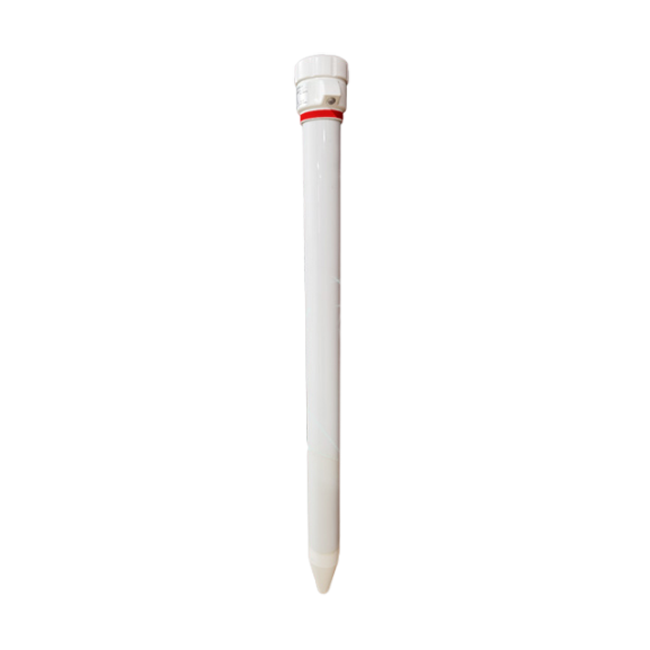 Multi-Depth Soil Sensor RS485
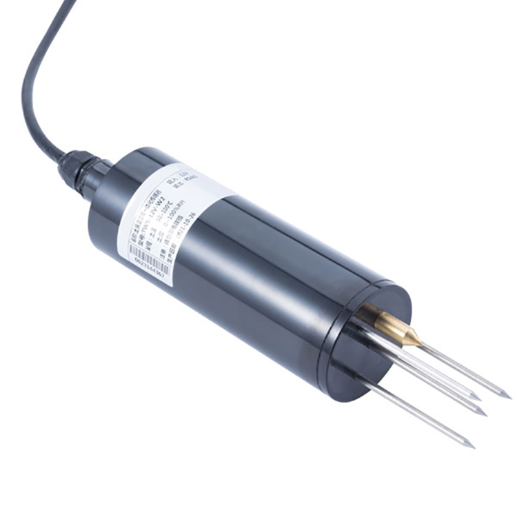 TDR Soil Moisture Sensor
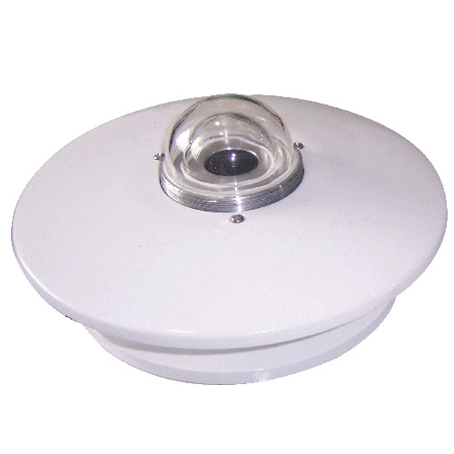 Pyranometer Solar Radiation Sensors
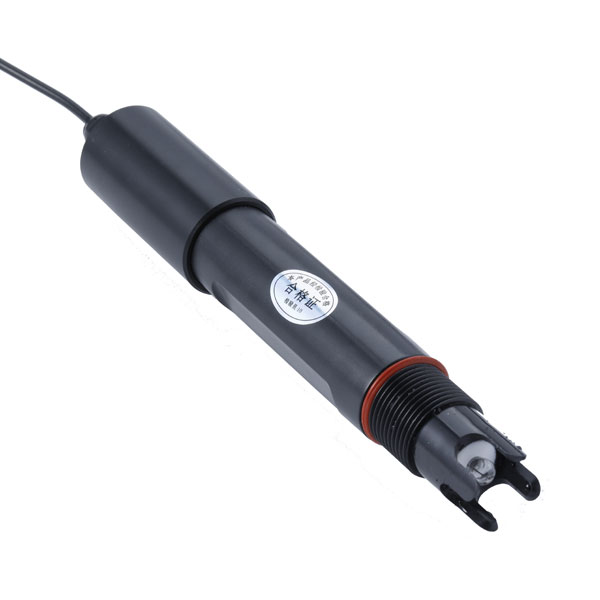 Soil ph sensor
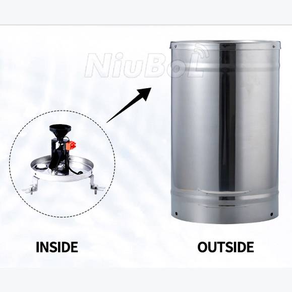 Tipping Bucket Rain Gauge
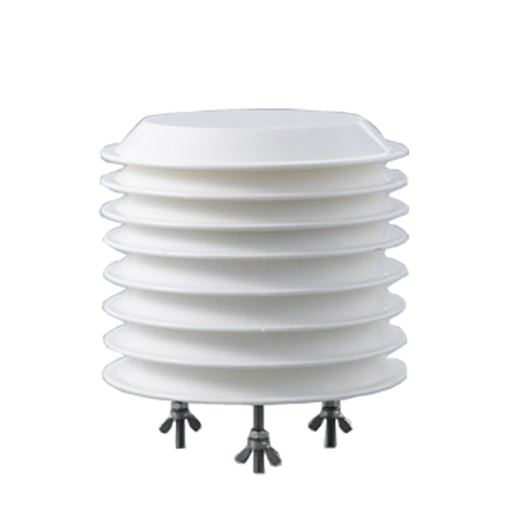 Air Temperature and Humidity Sensor


Screenshot, WhatsApp to identify the QR code
WhatsApp number:+8615367865107
(Click on WhatsApp to copy and add friends)

