





— Download —
 Consumer hotline +8618073152920
WhatsApp:+8615367865107
Address:Room 102, District D, Houhu Industrial Park, Yuelu District, Changsha City, Hunan Province, China
All products


Select NiuBoL ultrasonic anemometers for 2D wind, 3D flow or compact weather stations. Compare axes, power and data timing before requesting an integration quotation.
Tel/WhatsApp:+8615367865107
Email:Arvin@niubol.com +Nearly 100 partner companies in more than 75 countries. We are committed to providing high-quality, practical products to meet your needs and help you solve problems. Our products comply with international standards and are certified with ISO, CE and RoHS.Product Details
Quick Answer: Select NiuBoL ultrasonic anemometers by the wind quantities and time resolution the project needs. A two-dimensional unit measures horizontal wind; a three-dimensional instrument also resolves vertical flow. An integrated weather sensor adds other environmental channels but is not automatically a 3D instrument. Check the required axes, output definitions and installation before comparing housings or port counts. Bearing-free wind measurement still requires suitable exposure and inspection.

| Project question | Suitable measurement arrangement |
|---|---|
| What is the horizontal wind speed and direction? | A 2D ultrasonic wind instrument with the required range and reporting method |
| Is vertical flow or a three-axis velocity vector required? | A 3D instrument exposing the required axis values and coordinate definitions |
| Are wind and other weather channels needed at one compact point? | An integrated weather sensor, provided its shared exposure and individual channels fit the project |
| Are fast turbulence or flux calculations required? | A measurement chain with verified raw outputs, sampling rate and synchronization; 3D capability alone is insufficient |
A wind-speed-only ultrasonic sensor is appropriate when direction is unnecessary. A two-axis anemometer reports horizontal speed and direction. A three-dimensional instrument also resolves vertical flow and is normally selected for research or specialised turbulence work. Integrated weather sensors add temperature, humidity, pressure, rainfall or light channels. These options are not interchangeable simply because all use ultrasonic wind measurement.
Eliminating moving bearings reduces wear, but it does not eliminate siting, cleaning or environmental limits. Ice, heavy contamination, nearby structures and severe precipitation can affect a measurement. Compare the rated range, low-wind response, update rate and model-specific environmental limits; identify whether any required heating is actually included.
Check the wind components separately from the total number of reported parameters. A seven-parameter weather sensor may report horizontal wind plus five non-wind quantities. It does not become a three-axis wind instrument because it returns more registers than a wind-only device.
For a compact remote station, the integrated package can reduce mounting and cabling. For a wind study, access to the required velocity components and their timing can matter more than additional weather channels. Compare those duties before deciding that one package can serve both.
| Parameter | NBL-W-21MUWS, 2D | NBL-W-3D-UWDS, 3D |
|---|---|---|
| Wind outputs | Horizontal speed and direction | Resultant speed, horizontal and vertical direction, and X/Y/Z velocity components |
| Speed range | 0-40 m/s | Resultant 0-60 m/s; X/Y/Z components -60 to 60 m/s |
| Direction range | 0-360 degrees | Horizontal 0-359 degrees; vertical -90 to 90 degrees |
| Resolution | 0.01 m/s; 1 degree | 0.01 m/s; 1 degree |
| Speed accuracy | +/-0.5 m/s at low speed; +/-1 m/s at high speed. Agree the applicable band boundary. | +/-(0.5 + 3% FS) m/s; confirm the full-scale basis for the signed axis ranges |
| Direction accuracy | +/-3 degrees at low speed; +/-5 degrees at high speed | +/-3 degrees |
| Supply and power | 12-24 VDC; 0.2 W | 9-24 VDC; 2 W average |
| Interface | RS485 Modbus; 9600 baud | RS485 Modbus; 9600 baud |
| Operating temperature | -40 to 70 degrees C | -40 to 80 degrees C |
| Housing protection | IP65; engineering plastic | IP66; metal construction |
The NBL-W-21MUWS configuration and NBL-W-3D-UWDS configuration have different channel sets, power demands and environmental limits. Use the specification for the actual model rather than applying a family-wide accuracy or enclosure rating.
The daily sensor energy at constant nominal power is approximately 4.8 Wh for a 0.2 W unit and 48 Wh for a 2 W unit. These calculations exclude the logger, communications and supply losses. A solar station designed around a compact 2D device may therefore need a different energy budget for the 3D configuration.
Mount the sensor where buildings, trees, towers and solar panels do not dominate the flow. The mast and boom should not sit directly in the prevailing upstream path. Record mounting height and north orientation. A sensor installed in a roof wake can deliver repeatable data that still does not represent the site.
A bridge, rooftop or industrial platform can have several locally different wind fields. Choose whether the measurement represents a particular work area or a wider exposure. Moving a sensor above an obstruction can improve that exposure but also change the location being measured; retain its position and height with the wind record.
An integrated assembly needs an additional placement check. An open wind position is not necessarily the right point for crop-zone air temperature or another environmental quantity. If those measurements belong at different heights or locations, separate instruments can be more useful than a compact package forced into one compromise position.
Leave acoustic paths unobstructed and support the cable so it cannot move into the sensing region. Inspect the final arrangement with adjacent antennas, panels and crossarms in place. A clear sensor on a bench does not establish clear airflow after installation on a busy mast.
The NBL-W-21MUWS uses 9600 baud, 8 data bits and no parity, with at least 1000 ms between communications. Match the supplied serial format, address and channel definitions before expanding a bus. Do not assume the same polling or register layout applies to every integrated or 3D model.
The 2D speed value uses 0.01 m/s per decoded count, while direction uses degrees. The NBL-W-3D-UWDS exposes six values: resultant speed, horizontal direction, vertical direction and three signed velocity components. Configure sign handling as well as decimal scaling. Treat a missing or invalid value according to that device's definition before calculating a vector.
A PLC, RTU or data logger must distinguish the sensor's update rate from the bus polling interval and the platform upload interval. Repeatedly reading a register does not prove that a new acoustic measurement has occurred. A fast network connection cannot recover fluctuations already averaged out inside an instrument.
Keep local acquisition running at the required cadence when remote uploads are less frequent. Ask which records are instantaneous values, interval means or calculated extremes. Without those definitions, two platforms can display different wind values from the same sensor without either having an electrical fault.
Ask for range, resolution, accuracy basis, update rate and low-wind behaviour for the exact model. A broad statement such as "high accuracy" is not an acceptance limit. Direction performance should identify the reference orientation and any dead sector created by supports. For 3D work, confirm vertical velocity range and the coordinate convention used in the data output.
Environmental scope matters as much as the nominal wind range. State minimum and maximum temperature, expected icing, salt exposure, dust, precipitation and lightning environment. Where heating is offered, include heater power in the station energy budget and confirm whether measurement performance changes while heating is active.
For a project with an operational wind limit, define the alarm quantity and its averaging period. Do not treat an unqualified peak value as interchangeable with a defined gust statistic. Any crane, access or process decision also needs the appropriate control and safety arrangements; a Modbus wind channel alone does not establish a certified protective function.
With velocity components u, v and w, horizontal speed is the square root of u squared plus v squared. Three-dimensional resultant speed also includes w squared. For illustrative components of 3, 4 and 2 m/s, horizontal speed is 5 m/s while the three-dimensional resultant is approximately 5.39 m/s. These are different quantities, not competing calibrations of the same channel.
Coordinate orientation and sign must be agreed before interpreting the components. Do not assign geographic east, north or upward meaning merely from the letters X, Y and Z. Confirm how the installed instrument axes relate to the site's coordinate system and whether the receiving software rotates them.
Averaging also changes the result. Equal-duration velocities of +5 and -5 m/s on one axis have an average speed magnitude of 5 m/s but a zero resultant mean velocity on that axis. Choose scalar or vector processing for the intended statistic, and preserve the method with the exported data.
For turbulence or flux work, establish the required sampling rate, synchronization, raw component access and any additional measured quantities with the research method. Six available wind registers do not establish sonic-temperature output, high-rate synchronized acquisition or a complete flux system. Request evidence for those functions before selecting the instrument for that duty.
Before fixing the final orientation, verify the instrument's zero mark against the agreed direction reference. Check level and axis alignment where relevant, then compare decoded values at the local logger and final application. A repeated direction offset calls for an orientation and convention check before a software correction.
A colocated comparison can reveal unit, scaling and gross response problems, but matching one calm reading is not a field calibration across the specified range. Include varying conditions and comparable averaging. For an established record, retain a useful overlap when changing instrument architecture.
Inspect transducers, fasteners, contamination and cable restraint during service. An IP65 or IP66 housing is not a guarantee of ice-free acoustic paths. Include icing conditions and any required heating capability in the selection review; do not assume a heater from the temperature range alone.
Not necessarily. Additional temperature, humidity or rainfall channels do not provide vertical wind velocity. Select by the actual wind axes and outputs, not by the total parameter count.
When the project needs horizontal wind speed and direction and the instrument meets the required range, timing and exposure. Specify a 3D arrangement when vertical flow or three-axis components are part of the measurement task.
No. The research method must also be supported by sampling rate, synchronization, raw outputs and any other required quantities. A channel list and Modbus interface do not establish that complete capability.
A three-dimensional resultant includes the vertical component. Horizontal speed does not. Confirm which quantity the logger stores before comparing readings or assigning an alarm limit.
Only if the instrument supplies new valid measurements at that cadence and the permitted communications support it. Polling, internal measurement, averaging and upload are separate timing stages.
No. Contamination, ice, loose mounting and changed airflow exposure still need inspection. Compare service requirements for the actual location, including whether the sensing region remains safely accessible.
Specify the required axes and statistics, ranges, time resolution, environmental conditions, supply and receiving system. Include mounting, direction reference, cable, maintenance access and the intended comparison method so NiuBoL can review the appropriate architecture.
Choose ultrasonic anemometers by the wind quantities needed, then match the model's range, timing, power and installation to the project. Compact weather integration, horizontal wind monitoring and three-axis flow measurement solve different tasks. Send NiuBoL the required outputs and site arrangement to compare suitable configurations.
Sensors & Weather Stations Catalog
 Agriculture Sensors and Weather Stations Catalog-NiuBoL.pdf
Weather Stations Catalog-NiuBoL.pdf
Agriculture Sensors Catalog-NiuBoL.pdf
Water Quality Sensor Catalog-NiuBoL.pdf
Related recommendations
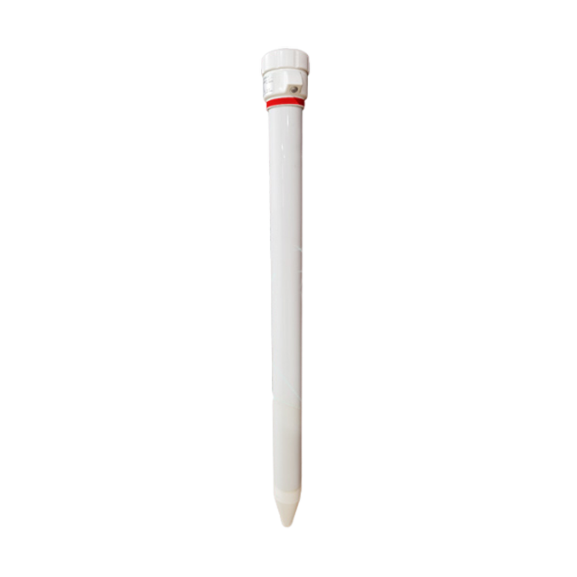 Multi-Depth Soil Sensor RS485
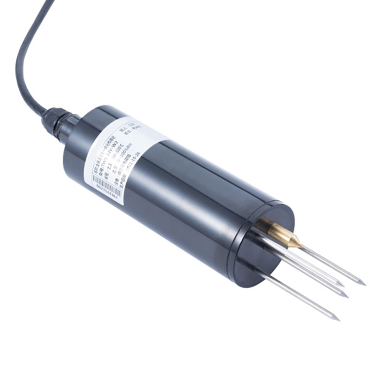 TDR Soil Moisture Sensor
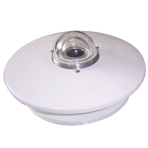 Pyranometer Solar Radiation Sensors
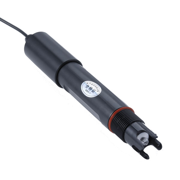 Soil ph sensor
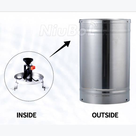 Tipping Bucket Rain Gauge
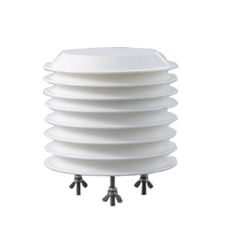 Air Temperature and Humidity Sensor


Screenshot, WhatsApp to identify the QR code
WhatsApp number:+8615367865107
(Click on WhatsApp to copy and add friends)

