





— Download —
 Consumer hotline +8618073152920
WhatsApp:+8615367865107
Address:Room 102, District D, Houhu Industrial Park, Yuelu District, Changsha City, Hunan Province, China
All products

NiuBoL NBL-S-THR soil moisture and temperature sensor for root-zone monitoring. Plan probe depths, soil contact, Modbus RTU channels and field irrigation acceptance.
Tel/WhatsApp:+8615367865107
Email:Arvin@niubol.com +Nearly 100 partner companies in more than 75 countries. We are committed to providing high-quality, practical products to meet your needs and help you solve problems. Our products comply with international standards and are certified with ISO, CE and RoHS.Product Details
Quick Answer: A root-zone soil moisture sensor is useful only when its sensing volume represents the soil and depth being managed. The NiuBoL NBL-S-THR combines soil moisture and temperature measurement with a selected RS485 or analog output. For agricultural irrigation, decide the soil zones and installation depths before deciding how many probes to buy; one accurate probe beside a dripper does not describe the whole field.

The NBL-S-THR measures the soil's dielectric response to obtain moisture information and provides a temperature channel. It does not directly measure the energy needed for roots to extract water. Where an irrigation decision depends on soil water potential, use an appropriate water-potential instrument rather than relabelling a moisture percentage as suction.
Separate fields or compartments with different soil texture, irrigation layout or crop development before assigning probe locations. A sandy section and a clay-rich section can have different useful moisture intervals even when the instruments show the same number. Combining those locations into one average can conceal the area that needs attention.
A multi-depth installation can distinguish a surface wetting event from water moving deeper through the active root zone. The shallow point may respond first while the deeper point remains unchanged. That pattern needs to be interpreted against the irrigation event and soil profile, not immediately classified as a failed lower probe.

The configuration described here provides soil moisture and soil temperature. Specify an EC-capable configuration separately when electrical conductivity is also required. Similar probe bodies can have different channel sets, voltage spans and register maps; connector shape alone is not an electrical specification.
For a root-zone soil moisture sensor installation, define the required output, receiving controller, supply voltage, cable route and burial arrangement for each location. A wired soil sensor does not provide its own wireless backhaul. A gateway or data logger is a separate part of the installation when the readings must be sent to a remote platform.
| Parameter | Configuration |
|---|---|
| Soil moisture range | 0-100% |
| Soil temperature range | -50 to +100 °C |
| Resolution | 0.1% moisture; 0.1 °C temperature |
| Nominal accuracy | ±3% moisture; ±0.5 °C temperature |
| Supply | 12-24 V DC |
| Output options | RS485, 4-20 mA or 0-5 V; select the required version |
| Receiver load | Current input: no more than 250 ohms; voltage input: at least 1 kohm |
| Nominal consumption | Approximately 0.3 W; size the complete acquisition channel for its actual output configuration |
| Operating environment | -40 to +80 °C |
| Probe protection | IP68; field connectors and cable joints require their own suitable sealing |
| Cable specification | Specify length, sheath and termination for the installation; use the pinout for the selected output |
The temperature measuring range and operating-environment interval are different specifications. A displayed temperature scale extending to +100 °C does not qualify the instrument for continuous operation in a +100 °C environment.

For drip irrigation, choose and record the probe's position relative to the emitter and plant row. A point inside the immediate wetting zone may rise quickly while another point between emitters remains drier. Neither reading is automatically wrong. Changing the location without recording it breaks the comparison with the previous irrigation history.
For a vertical profile, select depths from the crop's active roots and the management question. An upper point can show replenishment, while a deeper point helps show whether water reaches or passes beyond the intended zone. There is no single installation depth or spacing that is suitable for every crop, soil and irrigation method.

Insert the rods into undisturbed soil where possible. Do not rock the body sideways to enlarge the insertion path, force the rods against stones or leave an open cavity around them. For a buried installation, expose a suitable soil face, insert the probe into that face and restore the excavation without leaving a loose preferential water path.
Keep the cable clear of cultivation tools and protect the exit from repeated pulling or sharp bending. Locate serviceable connections where they can be inspected. The probe's IP68 rating does not make an improvised cable extension or an unsealed field splice suitable for burial.

The instrument's 0-100% scale is not a recommended irrigation setpoint interval. Establish a useful operating band from the soil, crop and wetting response at that location. Record readings after irrigation and drainage, compare them with independent soil observations and identify the depletion pattern between irrigations.
When a soil-specific calibration is required, compare the sensor with an independently determined volumetric water content over more than one moisture condition. A single wet sample cannot establish the complete response. Keep the sampling volume, soil packing and sensor contact representative; calibrating loose disturbed soil and then installing in a compacted profile introduces another difference.
Soil moisture readings alone do not forecast crop yield. Use them as an input to irrigation and crop management, alongside rooting depth, weather, growth stage and other relevant observations. The practical value is detecting whether the managed root zone is being replenished and depleted as intended.

The RS485 version uses Modbus RTU. Match the 9600 bit/s, eight-data-bit, no-parity format and the supplied stop-bit setting. Allow more than 1000 ms between transactions for this sensor. Assign and label each device address before several probes are connected to the same bus.
A function-03 read from 0x0000 returns two registers: soil temperature followed by soil moisture. Apply the 0.1 scale to valid values. For example, 180 represents 18.0 °C and 272 represents 27.2% moisture. Preserve the depth and location with the value so that a controller cannot confuse a lower probe with an upper one after maintenance.
Check for the 0x7FFF invalid or missing-data marker before scaling. Converting that marker into 3276.7% would produce an apparently numeric reading that is not a valid moisture measurement. Keep invalid data distinct from a genuine dry reading, and define how the irrigation controller should handle the affected channel.
For the 4-20 mA moisture channel, the 0-100% conversion is moisture = (I - 4) / 16 × 100. Thus 12 mA is 50% of the configured scale. That electrical check does not prove that the installed soil actually has 50% volumetric water content. The 0-5 V version needs the corresponding voltage conversion; do not select that scale for a differently ordered voltage span.

If every depth remains unchanged during an irrigation event, first check that water actually reached the monitored zone. Then examine device addresses, raw register values or analog signals and channel timestamps. A repeated last-valid value can look stable even after communication has stopped.
If only one point differs, inspect its soil contact, depth, emitter distance and local texture before changing its calibration. Check whether a recent cultivation operation, a cable repair or probe replacement changed the installation. A uniformly shifted display after maintenance may be a channel-scaling problem rather than a change in soil water.
For an agricultural soil moisture sensor quotation, send NiuBoL the crop and soil context, number of management zones, planned depths, selected output, controller type and cable route. Separate the probe quantity from any logger, gateway, power supply and irrigation-control hardware so that the proposed system covers the full installation.

Base the number on distinct soil and irrigation zones, then on the depths needed within those zones. A large uniform area and a smaller field with contrasting soils can need different layouts. Field area alone is not enough to determine probe quantity.
Not without checking the soil and crop conditions. Establish the useful moisture band and irrigation response locally. A threshold copied from another texture or rooting depth can produce a different water-availability decision.
No. The channel set is part of the ordered configuration. The NBL-S-THR configuration specified here provides temperature and moisture; an EC measurement requires the appropriate EC-capable sensor and receiving channel.
No. RS485 is a wired interface. Remote access requires a compatible logger or gateway with the required backhaul. Specify the field sensor interface and remote transmission arrangement separately.
No. Evaluate the connector and splice arrangement separately. Use suitable sealed terminations and cable protection for the intended burial and water exposure.
Verify identity and output, check channel scaling and invalid-data handling, then observe a representative installed point through a wetting and drainage cycle. Record depth and emitter position with the result. A bench communications test alone cannot validate field placement.
The NBL-S-THR supports root-zone soil moisture and temperature monitoring when probe locations, depths and signal interpretation are kept consistent. A useful agricultural installation combines representative soil contact with locally established irrigation thresholds and individually identified channels. That provides a clearer basis for deployment than selecting probes by housing appearance or field area alone.
 NBL-S-THR-Soil-temperature-and-moisture-sensors-Instruction-Manual-V4.0.pdf
Sensors & Weather Stations Catalog
 Agriculture Sensors and Weather Stations Catalog-NiuBoL.pdf
Weather Stations Catalog-NiuBoL.pdf
Agriculture Sensors Catalog-NiuBoL.pdf
Water Quality Sensor Catalog-NiuBoL.pdf
Related recommendations
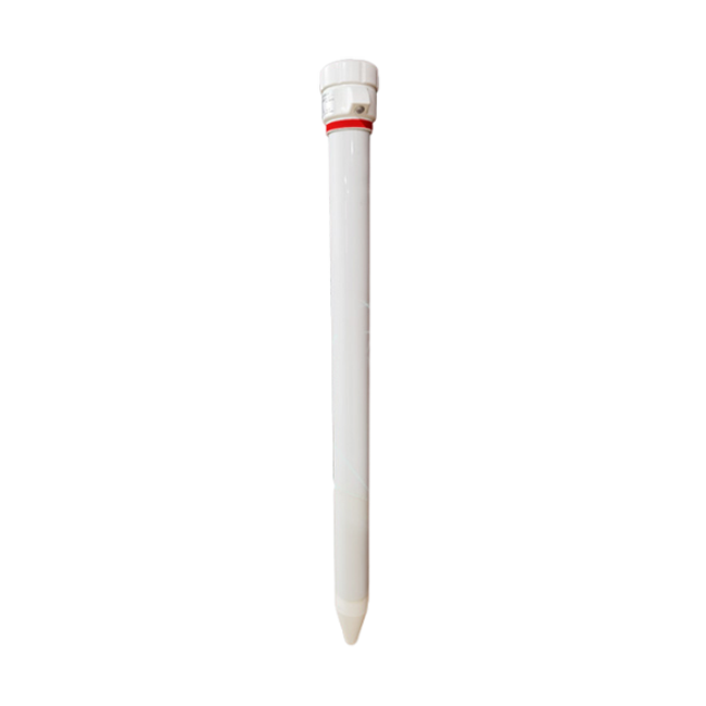 Multi-Depth Soil Sensor RS485
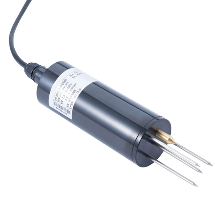 TDR Soil Moisture Sensor
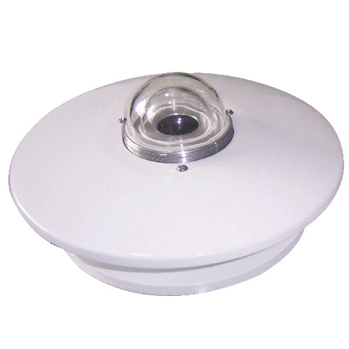 Pyranometer Solar Radiation Sensors
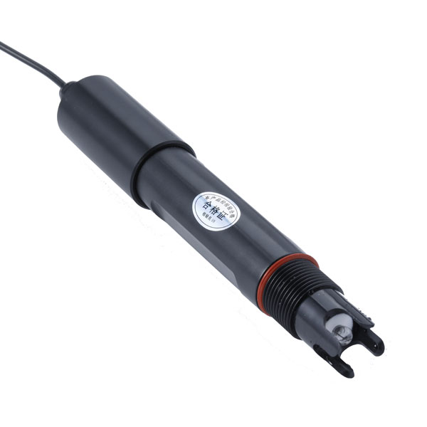 Soil ph sensor
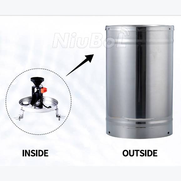 Tipping Bucket Rain Gauge
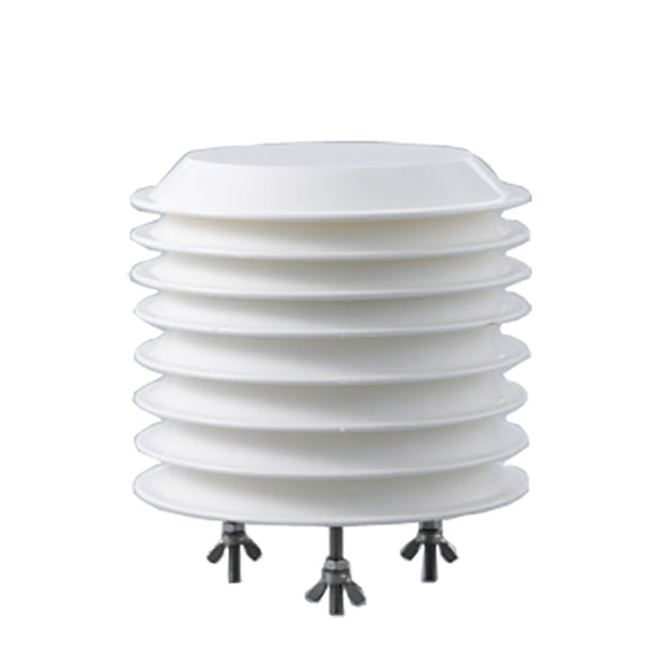 Air Temperature and Humidity Sensor


Screenshot, WhatsApp to identify the QR code
WhatsApp number:+8615367865107
(Click on WhatsApp to copy and add friends)

