





— Download —
 Consumer hotline +8618073152920
WhatsApp:+8615367865107
Address:Room 102, District D, Houhu Industrial Park, Yuelu District, Changsha City, Hunan Province, China
All products
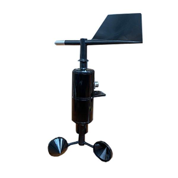
Evaluate a NiuBoL mechanical anemometer manufacturer offer for field weather projects. Check NBL-W-WSDS range, direction reference and output before requesting a quote.
Tel/WhatsApp:+8615367865107
Email:Arvin@niubol.com +Nearly 100 partner companies in more than 75 countries. We are committed to providing high-quality, practical products to meet your needs and help you solve problems. Our products comply with international standards and are certified with ISO, CE and RoHS.Product Details
Quick Answer: A mechanical anemometer manufacturer offer should identify the exact cup-and-vane assembly, ordered wind-speed span, electrical output and direction reference. The NiuBoL NBL-W-WSDS combines a three-cup rotor below a mechanical wind vane. Compare low-wind starting behavior, receiver compatibility and service access alongside the purchase price; a complete wind measurement needs both a suitable instrument and a correctly referenced installation.
Cup-and-vane instruments are familiar to operators, easy to inspect visually and compatible with common analog and RS485 acquisition systems. They are appropriate where moving parts and scheduled inspection are acceptable. An ultrasonic unit may be preferable where bearing wear, very low maintenance or special turbulence measurements dominate the requirement; the two technologies should not be compared only by unit price.
The wind-speed cups and direction vane provide different measurements. The rotor responds to airflow speed, while the vane aligns with airflow direction. Their starting characteristics also differ, so a stable vane indication does not demonstrate that the cups are measuring very light wind accurately.
The NBL-W-WSDS is a combined mechanical wind instrument, not an ultrasonic sensing head or a complete meteorological station. It needs an appropriate supply and acquisition interface. Rainfall, air temperature and remote communication are separate functions when the project requires them.
| Item | Specification or ordering requirement | Procurement consequence |
|---|---|---|
| Wind-speed span | 0-45 m/s or 0-70 m/s as ordered | Keep the span tied to analog scaling and the approved version. |
| Wind-speed accuracy | +/-(0.3 + 0.03V) m/s, where V is wind speed in m/s | The percentage term depends on reading, not full scale. |
| Wind-speed resolution / starting speed | 0.1 m/s / no more than 0.8 m/s | Review suitability for a low-wind observation task. |
| Direction span / resolution / accuracy | 0-360 degrees / 1 degree / +/-3 degrees | Agree the direction convention and reference alignment. |
| Vane starting speed | No more than 0.5 m/s | Direction near calm conditions still needs careful interpretation. |
| Supply options | 5, 12 or 24 VDC by ordered version | Do not assume every unit accepts a continuous 5-24 V range. |
| Output options | 4-20 mA, 0-5 V or RS485 Modbus RTU | Select and confirm the required electrical version. |
| Working environment | -40 to 50 degrees C; humidity up to 100% RH | Assess icing, exposed connections and local weather separately. |
| Wind-sensor housing requirement | Specify IP65 for the ordered assembly | Confirm the supplied housing and connection arrangement before approval. |
| Power demand / cable jacket | Confirm for the ordered supply, output and cable | Obtain the total load and cable suitability for the actual installation. |
The speed-accuracy expression gives +/-0.6 m/s at a reading of 10 m/s and +/-1.2 m/s at 30 m/s. Those are arithmetic evaluations of the expression, not field test results. They help compare an offer without confusing the 0.1 m/s increment with measurement accuracy.
For a 4-20 mA wind-speed channel, W = (I - 4) x L / 16, where I is current in mA and L is the ordered span in m/s. At 12 mA, the result is 22.5 m/s for a 45 m/s span or 35 m/s for a 70 m/s span. Replacing one version with the other without changing the receiver can therefore create a plausible but wrong wind record.
For the 0-5 V speed version, W = Vout x L / 5. Confirm the ordered signal and input load before connection; do not infer a voltage span from the supply voltage. Current-output speed and direction channels also have different load limits: up to 600 ohms for speed and 250 ohms for direction in this configuration. Check the complete receiving circuits.
The RS485 version provides digital acquisition through Modbus RTU. For the matching two-register sequence, function 03 starts at 0x0000 and reads speed followed by direction. Verify speed conversion and the delivered firmware before assigning PLC or logger tags. A physical RS485 connection is not a complete server interface.
Use 9600 bps, eight data bits and no parity, with the delivered one- or two-stop-bit setting. Allow at least 1000 ms between communications. If several devices share the bus, commission addresses individually before combining them, and keep the device address associated with its field location.
Install this assembly vertically with the wind vane above the cup rotor. Its white south reference mark is aligned with geographic south. Do not use a north-mark instruction from a different wind sensor merely because both instruments return degrees.
A compass reading needs the appropriate treatment of local magnetic declination when geographic alignment is required. Keep nearby steelwork and electrical equipment in mind when establishing the reference. Record the final orientation and verify the receiver's indication at known vane positions before relying on a directional display.
Confirm whether the downstream application uses the meteorological direction from which wind arrives and how it represents north at the 0/360-degree boundary. A map arrow showing where air travels can otherwise appear reversed even when the sensor orientation is correct.
Direction averages also need circular treatment. Equal observations at 359 and 1 degrees are close to north, not an arithmetic average of 180 degrees. Use an appropriate directional calculation in the receiving software and define the treatment of calm or unavailable periods. A corrected vane alignment cannot repair an unsuitable averaging algorithm.
Check the final mast arrangement for nearby roofs, trees, booms and the station's own solar panel. Airflow disturbed by an obstruction can produce repeatable readings that do not represent the intended site. State the observation height and surroundings instead of treating a successful bench response as field acceptance.
Inspect free cup and vane movement, bearing noise, physical damage, bird contamination and cable strain. Increased starting friction can suppress light-wind data before it creates an obvious failure. Trend calm-period behaviour and compare with a nearby reference when available. Lubrication or factory service should follow the supplied manual rather than an improvised field treatment.
Distinguish starting behavior from failure. In very light air, the vane may retain a previous direction or the cups may remain stationary. If the observation requires reliable conditions below the stated starting speeds, review another suitable sensing configuration rather than assuming a display resolution guarantees that capability.
| Observed behavior | Checks before replacing the assembly |
|---|---|
| Persistent zero speed | Rotor obstruction, low airflow, electrical output, supply and receiver configuration |
| Direction offset after maintenance | Reference mark, mounting rotation and any software offset applied twice |
| Direction jumps around north | 0/360 wrap handling, averaging and actual vane movement |
| Analog speed differs after replacement | Ordered span, electrical scale and receiving input type |
| Both digital quantities disappear | Common supply, cable, serial settings and bus address |
Use a suitable wind reference or agreed test when measurement performance must be demonstrated. Spinning the cups by hand confirms movement and may show an output response; it does not establish the airflow speed or calibrate the instrument. Likewise, rotating the vane through known positions checks orientation and acquisition rather than wind-tunnel performance.
When comparing a manufacturer offer, check whether the quoted scope includes only the sensor head or also the mounting adapter, compass, cable, surge devices and data collector. Confirm the stated starting speeds for both rotor and vane, because low-wind performance cannot be inferred from the maximum range.
Request the approved model, speed span, supply, output and enclosure requirement together. Specify IP65 for the ordered wind-sensing assembly and resolve the supplied version before acceptance. Assess the field joints, mast bonding and acquisition enclosure separately; neither a housing rating nor a broad lightning-resistance statement replaces those design decisions.
For repeat installations, identify whether the complete head or individual service parts will be replaced and who performs the work. Record the accepted direction reference, channel configuration and any service event that can change the readings. Do not apply unapproved oil, solvent or mechanical adjustment as a substitute for the correct service procedure.
Send NiuBoL the monitoring task, wind band, low-wind requirement, output, receiver, mast arrangement and cable route. Include the required comparison or calibration records. An agricultural observation point and an operational alarm project may need different verification and receiving logic even when they use a mechanically similar sensor.
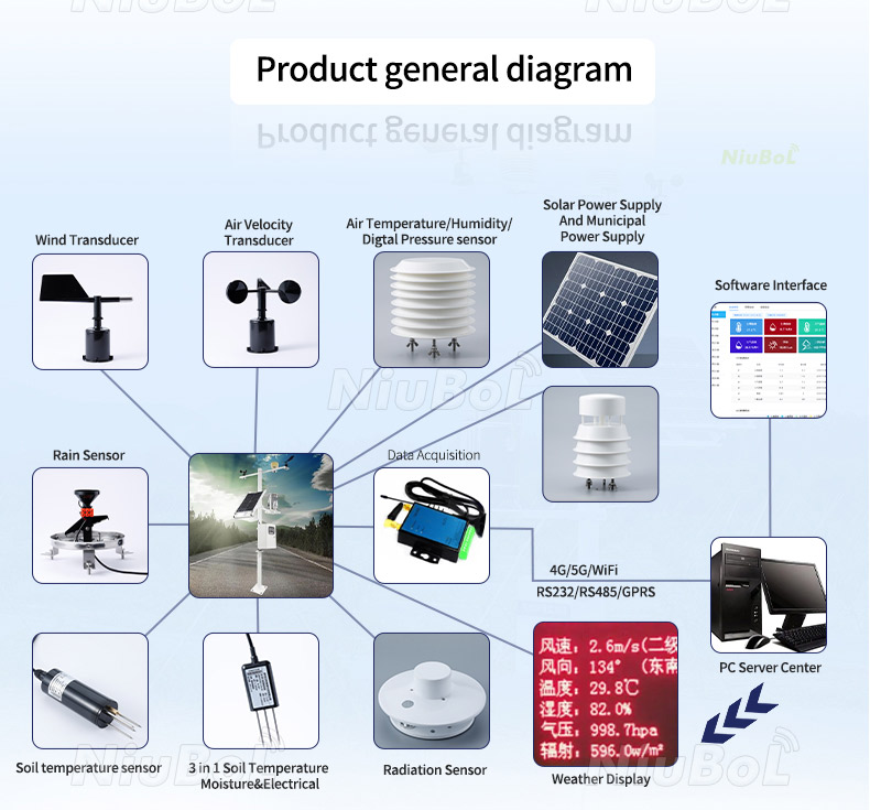
The diagram above includes optional acquisition equipment and other sensor types. The modular station below illustrates a possible wider layout with separate instruments, not additional channels inside the NBL-W-WSDS or an automatic list of items in the wind-sensor order.

For this combined cup-and-vane assembly, use NBL-W-WSDS together with the selected span, supply and output. The model identity must agree across the quotation, delivered label and receiving configuration.
Not without checking scaling and the approved configuration. At 12 mA, the two specified spans represent 35 and 22.5 m/s respectively. Confirm the replacement version before retaining the old receiver settings.
For this assembly, align the white south mark with geographic south and install the vane above the rotor. Verify displayed directions after mounting rather than assuming a convention from another model.
Inspect reference alignment and the handling of the 0/360 boundary. A simple arithmetic average can turn 359 and 1 degrees into a false southerly result. Use an appropriate circular calculation and define calm-period handling.
No. Rotor and vane starting characteristics are separate from output resolution. Evaluate the required low-wind observations against those characteristics and suitable performance evidence.
Specify IP65 for the ordered wind-sensing assembly and confirm the matching housing and connection arrangement. Protect cable joints and other station equipment separately; the sensing head's requirement does not rate the whole installation.
Compare the same speed span, starting behavior, output, supply, housing requirement, cable, mounting, verification and service scope. Include any separate logger or station equipment so a bare sensing head is not compared with a complete installation.
A mechanical anemometer manufacturer should provide an identifiable configuration and a workable commissioning and service scope. For the NBL-W-WSDS, keep span and receiver scale aligned, establish the south reference and inspect the moving parts and final airflow exposure. Those checks help NiuBoL and the project team supply a useful wind channel rather than only a compatible mounting head.
Prev:NBL-GS01 Fruit and Stem Growth Sensor RS485 | NiuBoL
Next:PAR Sensor for Greenhouse/Farm Plant Growth Measurement 0-5V/RS485/Modbus
Sensors & Weather Stations Catalog
 Agriculture Sensors and Weather Stations Catalog-NiuBoL.pdf
Weather Stations Catalog-NiuBoL.pdf
Agriculture Sensors Catalog-NiuBoL.pdf
Water Quality Sensor Catalog-NiuBoL.pdf
Related recommendations
 Multi-Depth Soil Sensor RS485
 TDR Soil Moisture Sensor
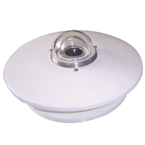 Pyranometer Solar Radiation Sensors
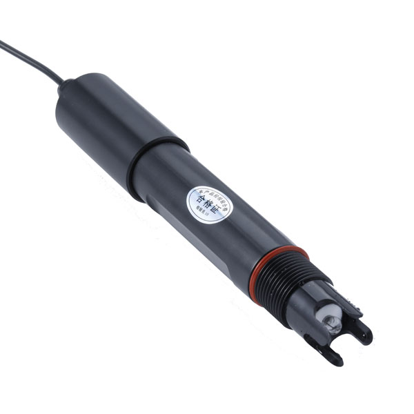 Soil ph sensor
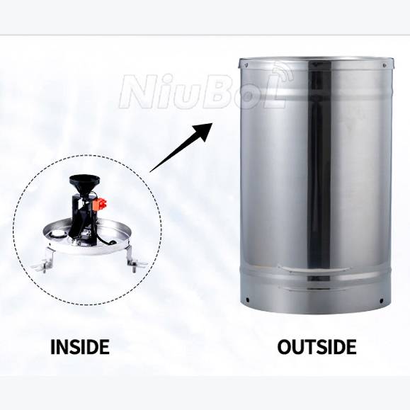 Tipping Bucket Rain Gauge
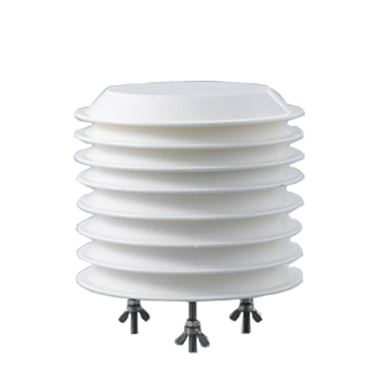 Air Temperature and Humidity Sensor


Screenshot, WhatsApp to identify the QR code
WhatsApp number:+8615367865107
(Click on WhatsApp to copy and add friends)

