





— Download —
 Consumer hotline +8618073152920
WhatsApp:+8615367865107
Address:Room 102, District D, Houhu Industrial Park, Yuelu District, Changsha City, Hunan Province, China
All products


Specify a NiuBoL direct solar radiation sensor for solar-resource studies. Check tracking alignment, detector output and data acquisition before requesting a quotation.
Tel/WhatsApp:+8615367865107
Email:Arvin@niubol.com +Nearly 100 partner companies in more than 75 countries. We are committed to providing high-quality, practical products to meet your needs and help you solve problems. Our products comply with international standards and are certified with ISO, CE and RoHS.Product Details
Quick Answer: A NiuBoL direct solar radiation sensor uses a narrow-view optical tube and solar tracking to measure direct normal irradiance. Choose this arrangement when a solar-resource or research project needs the direct beam, rather than only global horizontal or fixed array-plane irradiance. The detector range is 0-2000 W/m2 with a low-level thermopile signal; tracking, signal conditioning and logger configuration must be specified as parts of the measurement.

| Parameter | Specification |
|---|---|
| Measured quantity | Direct normal solar irradiance |
| Measuring range | 0-2000 W/m2 |
| Thermopile signal | 0-20 mV |
| Sensitivity | 7-14 microvolts per W/m2; use the individual calibration coefficient |
| Response at 99% | Up to 15 seconds |
| Supply for powered version | 12 VDC |
| Conditioned-output option | 0-5V; specify the required output with the order |
| Annual sensitivity stability | +/-1% rate of sensitivity change |
| Operating environment | -45 to 45 degrees C |
| Instrument cable | 2.5 m |
| Assembly weight | 5 kg |
Specify the required accuracy grade and calibration record with the quotation. Annual sensitivity stability describes a change over time, not the complete measurement uncertainty of a field installation. Tracking error, optical contamination and the acquisition channel also affect the result.
Direct normal irradiance is only one component of the solar resource. A complete research station may also use a horizontal pyranometer and a shaded instrument for diffuse radiation. The required combination depends on the energy model or scientific method. Do not infer all components from one direct sensor without a defined calculation and supporting data.
For a PV project, specify whether the analysis concerns direct normal, global horizontal or plane-of-array irradiance. These quantities have different sensor geometry. The direct tracker should not be mounted or labelled as if it were a fixed plane-of-array device.
Power and signal cables must allow tracker movement without twisting, snagging or pulling connectors. Observe a full movement range after installation. Provide a safe service position for cleaning the optical window and checking desiccant. Access planning is part of measurement quality because an unreachable window will not be cleaned regularly.
For a horizontal surface, the direct contribution is the direct normal irradiance multiplied by the cosine of the solar zenith angle. Global horizontal irradiance includes both the horizontal direct contribution and diffuse horizontal irradiance. As a simplified numerical example, 800 W/m2 of direct normal irradiance at a 60-degree zenith angle contributes 400 W/m2 horizontally; with 100 W/m2 of diffuse horizontal irradiance, the corresponding global value is 500 W/m2.
This relationship explains why the direct instrument and a level pyranometer need not show the same number. It is a component comparison under matched conditions, not a universal conversion from one instrument to every PV measurement. An inclined array has a different plane, and its received irradiance also depends on diffuse and reflected contributions.
A solar-resource campaign may need the direct channel to characterize the beam component. A radiation research station may use it alongside global and diffuse instruments for component checks. A PV performance project that needs only fixed plane-of-array irradiance may be better served by an appropriately mounted pyranometer, without adding a tracker that the analysis does not use.
The optical tube limits the field of view so the thermopile receives radiation from the solar disc and a narrow sky region. That makes tracker orientation part of the measurement. A stationary or poorly aligned tube will under-read even when the sensing element is functioning correctly.
Choose a site with an unobstructed solar path through all seasons. Level and orient the tracker using the installation method, then verify the light spot and tracking movement. The base must remain stable under wind and vibration. Smoke, fog and local shading change the measured direct radiation and should be considered when interpreting a low value.
Establish the base level and geographic reference before adjusting the tube. Use the latitude, solar-time and seasonal setup method applicable to the supplied tracker; do not substitute a civil clock setting for true solar time where the instructions require the latter. Verify the sighting indication rather than accepting motion alone as proof of alignment.
Observe tracking at more than one solar position. An arrangement that appears correct at commissioning can lose the beam later because of orientation, seasonal adjustment or a moving obstruction. Check the cable's movement allowance and the mount through the intended travel without pulling the optical assembly.
The complete tracker and electronics power demand must be established for an off-grid station, including starting and moving conditions. A detector consumption figure is not a sufficient basis for sizing the tracker supply, solar panel or battery. Request the assembled package's operating requirements instead of assigning one small component's consumption to the whole station.
The thermopile's millivolt signal needs a suitable low-level acquisition channel. Check input range, differential measurement capability, noise and the individual sensitivity coefficient. An analog input intended only for a larger transmitter voltage is not automatically adequate for the native detector signal.
With sensitivity in microvolts per W/m2, irradiance equals 1000 x output in mV / sensitivity. For example, 6 mV and an individual coefficient of 10 microvolts per W/m2 give 600 W/m2. This illustrates conversion only; 10 is not a coefficient to apply to every instrument.
If the ordered package uses a conditioned 0-5V output, use its documented span and wiring instead. Keep that conversion distinct from the raw thermopile formula. Confirm whether the quotation includes the conditioning electronics, tracker controls and instrument cables, rather than treating every listed signal as a simultaneous output on the same connector.
A station using RS485 Modbus RTU still needs an appropriate acquisition interface for this instrument. Specify a compatible analog input or a documented digital conversion assembly; an RS485 port on the logger cannot directly read a passive millivolt signal. Any Modbus map must belong to the supplied interface, not to a different NiuBoL radiation sensor.
Time-align the direct channel with complementary radiation and plant data. A cloud edge can change the beam between successive readings, while the specified 99% response is up to 15 seconds. Compare matching observation and averaging periods before attributing a short-lived difference to calibration.
| Observed behavior | Inspection that helps distinguish the cause |
|---|---|
| Sudden low value in otherwise clear conditions | Check optical alignment, a passing shadow, supply and acquisition before changing sensitivity. |
| Low values recur at a similar solar position | Review the horizon, local structures and tracker geometry across the day's path. |
| Signal remains plausible but gradually declines | Inspect the quartz window, internal condensation and calibration history. |
| Electrical signal is present but the logger value is wrong | Check the selected input span, coefficient, units and any transmitter conversion. |
Check the desiccant and enclosure seals as well as the outer optical surface. Inspect the quartz window at the start of observation work and use the specified gentle optical-cleaning method. Check tracking monthly and arrange sensitivity recalibration after more than two years; a project quality plan may require additional checks. Recheck alignment after disturbance rather than waiting for the next calendar inspection.
A useful field comparison needs suitable sunlight, a reference with known calibration and comparable timing. Keep sky-condition and tracking observations with the comparison. A cloudy period or an obstructed beam cannot establish clear-sky alignment merely because both instruments produce nonzero values.
Only if the required quantity is direct normal irradiance. A fixed array-plane pyranometer receives radiation on the module plane, including components this narrow-view instrument does not independently measure. Select the geometry from the plant's analysis requirement.
No. Check that the optical axis follows the sun using the supplied alignment indication, and repeat at different solar positions. A moving but offset tracker can leave the detector outside the intended beam.
Specify the native 0-20mV signal or the ordered conditioned output, together with its conversion and power arrangement. Use an appropriate interface if the station communicates over Modbus. Do not copy a register map from a global-radiation transmitter.
Obtain the complete assembly's demand during its required operating states and include logger and communications loads separately. Size storage for the site's operating schedule and autonomy requirement. A detector-only power figure does not define the moving system's demand.
Provide required radiation components, site latitude, horizon conditions, output, receiving input and supply arrangement. Include the mounting platform, calibration requirement, complementary instruments and commissioning access so the quotation covers a functioning measurement rather than only the optical head.
Choose a direct solar radiation sensor when the project needs the beam component and can maintain the tracker and optical path. Specify alignment, detector conversion and complete power requirements together. NiuBoL can review the radiation components and logger inputs for the proposed station.
Sensors & Weather Stations Catalog
 Agriculture Sensors and Weather Stations Catalog-NiuBoL.pdf
Weather Stations Catalog-NiuBoL.pdf
Agriculture Sensors Catalog-NiuBoL.pdf
Water Quality Sensor Catalog-NiuBoL.pdf
Related recommendations
 Multi-Depth Soil Sensor RS485
 TDR Soil Moisture Sensor
 Pyranometer Solar Radiation Sensors
 Soil ph sensor
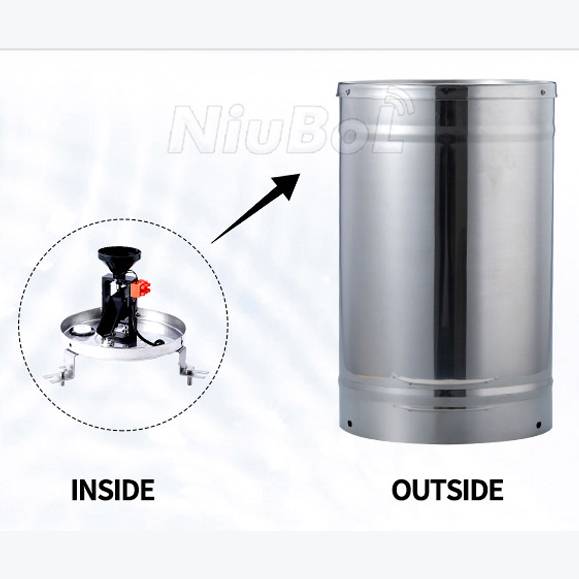 Tipping Bucket Rain Gauge
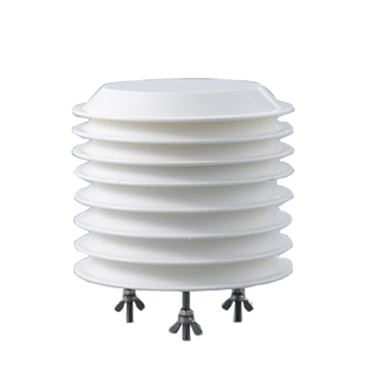 Air Temperature and Humidity Sensor


Screenshot, WhatsApp to identify the QR code
WhatsApp number:+8615367865107
(Click on WhatsApp to copy and add friends)

