





— Download —
 Consumer hotline +8618073152920
WhatsApp:+8615367865107
Address:Room 102, District D, Houhu Industrial Park, Yuelu District, Changsha City, Hunan Province, China
All products

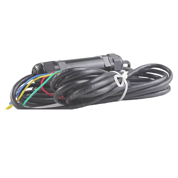
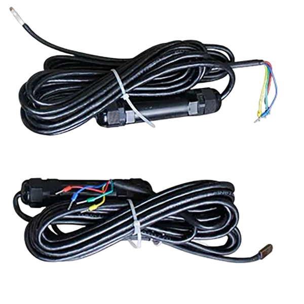
Specify a NiuBoL solar panel temperature sensor for PV module monitoring. Compare spans, powered outputs and logger inputs before requesting a matched configuration.
Tel/WhatsApp:+8615367865107
Email:Arvin@niubol.com +Nearly 100 partner companies in more than 75 countries. We are committed to providing high-quality, practical products to meet your needs and help you solve problems. Our products comply with international standards and are certified with ISO, CE and RoHS.Product Details
Quick Answer: A solar panel temperature sensor measures the module's rear surface at its contact point. The NiuBoL NBL-W-PPT configuration provides a powered temperature transmitter with selectable current, voltage or RS485 output. Specify the measuring span, supply and receiving input together. A backsheet contact pad connected to a transmitter is not electrically interchangeable with a bare thermistor or a PT100 resistance input, even when all three are described as temperature sensors.
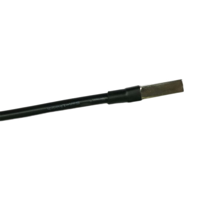
PV electrical output changes with cell temperature. A backsheet contact measurement gives operators a field indication that can be compared with irradiance, ambient temperature, wind and inverter output. It is useful for performance analysis, fault investigation and identifying unusual thermal behaviour. The reading is not the cell junction temperature, and it should not be substituted for a thermal-imaging inspection when the task is to locate a local hot spot.
Location matters. Install the sensor on the rear surface at the position defined by the project method, away from the frame and junction box unless the method calls for those locations. Use the supplied thermally conductive adhesive over a clean, dry surface. Cable strain must be carried by the module structure rather than by the sensing element.
For a new logger, choose an input supported by both the selected transmitter and the acquisition hardware. For a retrofit, start with the available input card and existing supply. The shape of the contact pad cannot tell the installer whether the cable carries resistance, voltage, current or digital communication.
This NBL-W-PPT configuration uses a thermistor sensing element and transmitter electronics. Identify the output on the order and on the field wiring schedule. Do not select a logger's PT100 mode merely because a different PV temperature product uses platinum resistance, and do not connect a powered output to an unpowered resistance-measurement input.
| Parameter | Configuration |
|---|---|
| Measurement span | -50 to 100 degrees C; alternative -20 to 50 degrees C |
| Temperature accuracy | +/-0.5 degree C |
| Supply options | 5, 12 or 24 VDC; specify the ordered version |
| Output options | 4-20mA, 0-2.5V, 0-5V or RS485 |
| Standard cable | 5 m |
| Voltage-output load | At least 1 kohm |
| Current-output load | 250 ohms maximum |
| Operating environment | -50 to 100 degrees C; 0-100% RH |
| Power consumption | 0.15 W |
These supply entries are ordering options, not a claim that every version accepts any voltage from 5 to 24 VDC. Likewise, a list of four interfaces does not establish that four simultaneous outputs are fitted. Ask for the exact supply/output combination and its connection arrangement.
Select the span around the expected module conditions, including cold starts and hot, weakly ventilated operation. A -20 to 50 degrees C channel should not be chosen just because the site's ambient air usually remains within that band. A sunlit module can be appreciably warmer than the nearby air.
For a 4-20mA output, T = Tmin + (I - 4) / 16 x (Tmax - Tmin), where current I is in mA. Apply the endpoints of the ordered sensor, not a default temperature span retained in the PLC program.
| Signal | -50 to 100 degrees C span | -20 to 50 degrees C span |
|---|---|---|
| 4 mA | -50 degrees C | -20 degrees C |
| 12 mA | 25 degrees C | 15 degrees C |
| 20 mA | 100 degrees C | 50 degrees C |
These are electrical scaling examples, not observations from a PV plant. A correct midpoint in one span is ten degrees different from the midpoint in the other. That error can remain unnoticed because either value may appear plausible on a monitoring screen.
For a 0-5V output, replace (I - 4) / 16 with V / 5. For a 0-2.5V output, use V / 2.5. The narrower temperature span gives a larger signal change per degree, but does not improve the stated +/-0.5 degree C accuracy or justify operation beyond its endpoints.
Test the receiver at low, middle and high electrical values using suitable equipment before evaluating the installed temperature response. Confirm the engineering units after data export as well as on the local display. An alarm limit expressed in the correct unit can still be wrong if the input uses the wrong span.
Use 4-20mA when the controller already has current inputs and cable runs are exposed to electrical noise. Voltage output suits shorter, controlled wiring. RS485 is useful when several digital channels share a logger, but address, register scaling and grounding must be planned. Confirm the ordered output before shipment because a logger cannot interpret a different electrical interface through software alone.
Route sensor cable away from DC power conductors where practical and protect it at module edges. Outdoor connectors, glands and junctions must be rated for the installation. Measure supply voltage at the sensor end, not only inside the cabinet. A channel that works during commissioning can become intermittent after thermal cycling if the cable is under tension.
For the current version, assess the complete receiving load against the 250 ohm limit. An input resistor of 250 ohms already consumes that stated load allowance; adding another device in series requires review. Confirm the powered-output wiring arrangement rather than assuming a generic two-wire loop.
For voltage acquisition, the input must meet the 1 kohm minimum load requirement. Shared return conductors and voltage drop can introduce an offset that resembles a temperature change. A software correction cannot reliably remove a varying ground or connection problem.
The NBL-W-PPT RS485 configuration uses Modbus RTU, 9600 baud, eight data bits and no parity, with at least 1000 ms between communications. Match the delivered stop-bit setting and check temperature scaling with the actual device. Verify negative-temperature representation during a suitable test rather than inferring it from a positive-temperature example.
A logger receiving RS485 still needs its own storage and remote communication arrangement. Do not infer cellular transmission, a cloud account or a particular platform connector from the sensor's digital interface. A compatible data logger or gateway is a separate part of the station.
Two sensors cannot be compared meaningfully when they are bonded at different relative positions or routed differently. Document the module row, sensor position, adhesive, cable route and installation date. On bifacial modules, confirm that the sensor and cable do not create unacceptable rear-side shading. Compare a new channel with neighbouring modules under stable irradiance before accepting it.
A well-bonded pad can accurately follow an unrepresentative module. Select the monitored module with the plant layout in mind: mounting type, ventilation, module construction, orientation and relevant shading. Do not average a roof-mounted module with an open-rack module and call the result one interchangeable plant temperature.
Conversely, a representative module does not compensate for poor thermal contact. Inspect the bond and provide cable strain relief before accepting a persistent temperature difference. The backsheet sensor installation guide addresses contact preparation, fixing and installation fault checks in more detail.
For bifacial modules, review the contact pad, transmitter and cable arrangement with the rear-side measurement objective. The equipment should not introduce unacceptable local shading or obstruct inspection. Keep the module position and physical sensor position with the channel record so replacement work preserves comparability.
Compare module temperature with irradiance and electrical power over matching time intervals. A hot module under strong sunlight is not automatically faulty. Look for persistent differences between comparable strings, unexpected temperature when irradiance is low, or a change after maintenance. Confirm unusual results with inspection and, when appropriate, thermal imaging.
For replacement, preserve the original location and update the serial and calibration record. If the adhesive layer, sensor construction or mounting position changes, treat the new channel as a changed measurement point and establish a new comparison baseline.
Use time-aligned records when relating temperature to irradiance and power. A short irradiance change may precede the module's temperature response, while the inverter record may use another averaging period. Misaligned intervals can create an apparent performance anomaly without a sensor fault.
Use the module manufacturer's applicable temperature coefficient and the chosen performance model when applying a temperature correction. No single loss-per-degree figure applies to every module technology. A contact temperature channel alone cannot establish recovered energy, degradation rate or the cause of an inverter power change.
A hot-spot investigation needs spatial information that one bonded point cannot provide. Use appropriate inspection and thermal methods when the question is a local cell, connection or junction-box anomaly. Adding a temperature pad is not a substitute for that diagnostic coverage.
For a quotation, give NiuBoL the expected temperature range, module and mounting type, logger input, supply, cable length and required number of representative points. Identify whether the order includes only the probe/transmitter or also the acquisition hardware and mounting consumables.
No. This thermistor-based configuration uses a transmitter with an ordered signal output. A direct PT100 input measures resistance. Specify the sensing construction and electrical interface together before substituting either device.
Choose a span that covers the expected module backsheet temperatures, not only ambient conditions. The -20 to 50 degrees C alternative is unsuitable where module temperature can exceed 50 degrees C. Verify both endpoints in the logger configuration.
Not without confirming that the ordered unit accepts that voltage or providing a suitable supply arrangement. The available supply options are not a universal voltage-tolerance statement for every unit.
No. Digital communication avoids analog span conversion at the input card, but the channel still depends on correct data interpretation, thermal contact and a representative module. Validate those separately.
Only where the monitoring method accepts that representation. Different mounting and ventilation conditions may need separate points. Agree the grouping before purchasing rather than deriving it from the number of spare logger channels.
Keep the temperature span, electrical interface, module identity and contact position consistent. Record the new sensor and bond, verify the channel and review comparable temperature trends before joining the new observations to the old history.
Specify the solar panel temperature sensor as a matched probe, transmitter and receiver. Choose a temperature span that covers the module, configure its output correctly and distinguish representative backsheet data from local fault inspection. Send NiuBoL the module conditions and logger input requirements to review the required version.
Prev:Direct Solar Radiation Sensor with Automatic Tracking
Next:CO2 sensor detection transmitter 4-20mA/RS485 for Gas Environmental Monitoring
Sensors & Weather Stations Catalog
 Agriculture Sensors and Weather Stations Catalog-NiuBoL.pdf
Weather Stations Catalog-NiuBoL.pdf
Agriculture Sensors Catalog-NiuBoL.pdf
Water Quality Sensor Catalog-NiuBoL.pdf
Related recommendations
 Multi-Depth Soil Sensor RS485
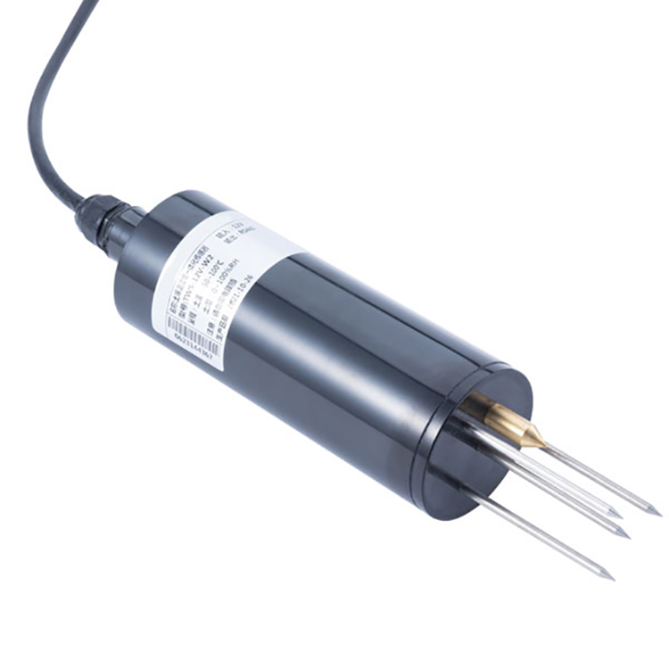 TDR Soil Moisture Sensor
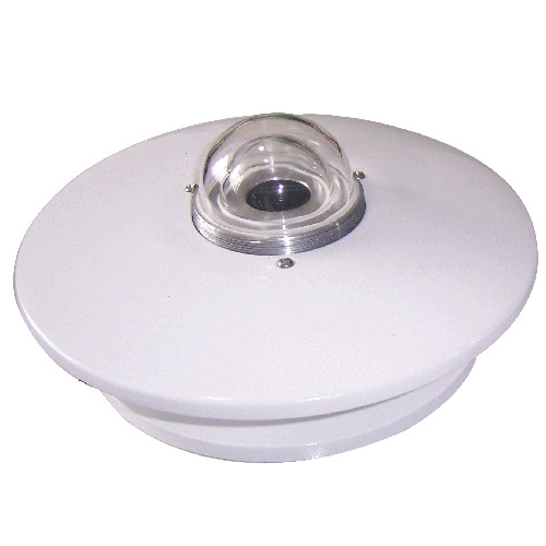 Pyranometer Solar Radiation Sensors
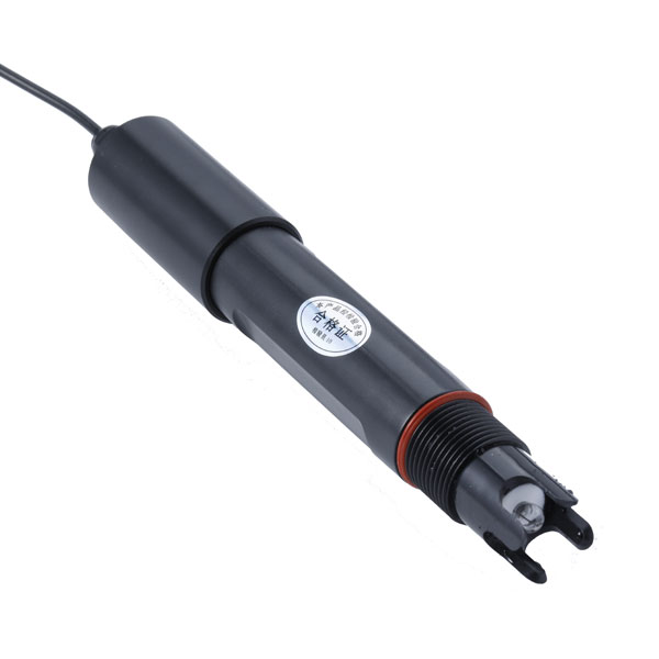 Soil ph sensor
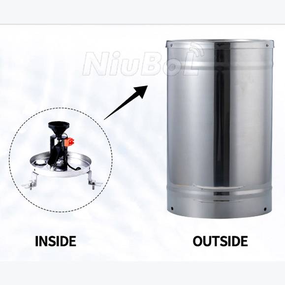 Tipping Bucket Rain Gauge
 Air Temperature and Humidity Sensor


Screenshot, WhatsApp to identify the QR code
WhatsApp number:+8615367865107
(Click on WhatsApp to copy and add friends)

