

— Download —
 Consumer hotline +8618073152920
 WhatsApp:+8615367865107
Address:Room 102, District D, Houhu Industrial Park, Yuelu District, Changsha City, Hunan Province, China
All products
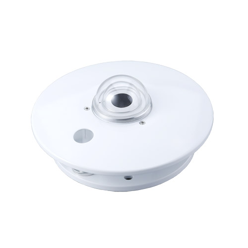
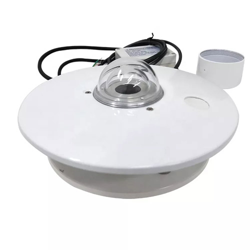
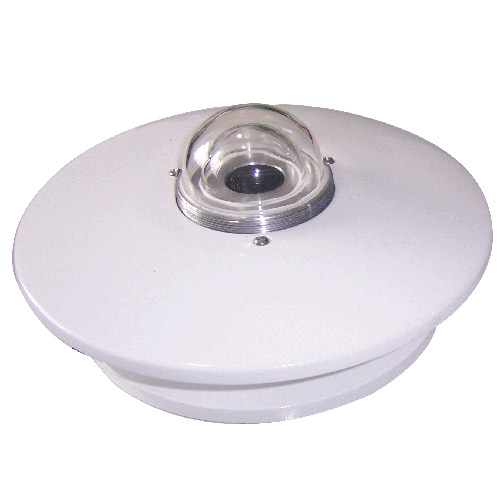
Configure a NiuBoL thermopile pyranometer for PV and weather monitoring. Match the measurement plane, output and calibration coefficient before requesting a quotation.
Tel/WhatsApp:+8615367865107
Email:Arvin@niubol.com +Nearly 100 partner companies in more than 75 countries. We are committed to providing high-quality, practical products to meet your needs and help you solve problems. Our products comply with international standards and are certified with ISO, CE and RoHS.Product Details
Quick Answer: A thermopile pyranometer measures hemispherical solar irradiance on its sensing plane. This NiuBoL configuration covers 0-2000 W/m2 across a 0.3-3 micrometre spectral band. Select the measurement plane and electrical output together: a passive millivolt signal needs its individual sensitivity coefficient, while a transmitter version uses the delivered voltage, current or RS485 conversion.
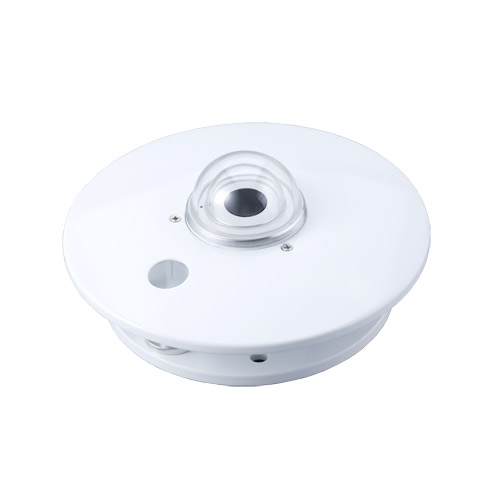
| Item | Specification |
|---|---|
| Range | 0-2000 W/m2 |
| Sensitivity | 7-14 microvolts per W/m2 |
| Spectral range | 0.3-3 micrometres |
| Outputs | 0-20mV, 0-2.5V, 0-5V, 4-20mA or RS485 |
| Supply | 5, 12 or 24 VDC for transmitter versions |
| Response time | Up to 35 s at 99% |
| Internal resistance | Approximately 350 ohms |
| Cosine response | Up to 7% at 10-degree solar altitude |
| Azimuth response | Up to 5% at 10-degree solar altitude |
| Temperature characteristic | +/-2% from -10 to 40 degrees C |
| Operating temperature | -40 to 50 degrees C |
An upward-facing unshaded pyranometer measures global irradiance on its plane. Reflected measurement uses a downward-facing geometry. Diffuse radiation requires the direct solar component to be shaded with suitable hardware and tracking or correction. The sensor does not change measurement type through software alone.
| Required quantity | Optical arrangement |
|---|---|
| Global horizontal irradiance | Upward-facing instrument on a level horizontal plane with the required unobstructed sky view. |
| Plane-of-array irradiance | Instrument aligned with the PV module plane, including tilt and azimuth. A separate horizontal channel is a different measurement. |
| Reflected irradiance | Downward-facing geometry with a defined view of the reflecting surface and appropriate mounting. |
| Diffuse horizontal irradiance | Suitable shading of the direct solar component, with the chosen shading method and correction requirements. |
The 0.3-3 micrometre band describes the instrument's solar spectral coverage. It does not provide separate ultraviolet, visible and infrared channel readings, and it is not a long-wave terrestrial radiation measurement. A project requiring a spectral quantity or a different radiation component needs the appropriate instrument or optical arrangement.
For PV performance monitoring, decide which array plane the reading must represent. For meteorological observations, preserve the horizontal geometry. Comparing those two values as though they should be identical can lead to unnecessary recalibration of correctly operating instruments.
The low-level 0-20mV thermopile signal preserves the native sensor response but needs a suitable high-quality differential input and careful cable practice. Transmitter voltage or 4-20mA outputs simplify some PLC installations. RS485 supports digital acquisition but still needs a model-specific register map.
For a passive thermopile, use the sensitivity on that sensor's calibration record. With sensitivity expressed in microvolts per W/m2 and measured voltage in mV, irradiance equals 1000 x voltage / sensitivity. As an illustration, 8 mV from a sensor with sensitivity 10 microvolts per W/m2 corresponds to 800 W/m2. The value 10 is an example, not a default coefficient for every instrument.
The stated 7-14 sensitivity interval is not an accuracy statement and is not a coefficient to average. When replacing a passive instrument, update the channel with its own calibration coefficient. Otherwise an unchanged logger program can produce a systematic scale error even though the new sensor is functioning correctly.
For a linear 4-20mA version spanning 0-2000 W/m2, 12 mA represents 1000 W/m2. Use the delivered transmitter scaling, not the passive-sensor sensitivity formula. The same principle applies to a voltage transmitter: confirm the actual voltage span before programming its receiving input.
The NBL-W-HPRS V3.0 digital version uses RS485 Modbus RTU acquisition. Its communication interval is at least 1000 ms. Serial compatibility does not remove the need to confirm range, units and the supplied register document.
Use the levelling device and recheck after mast work or foundation movement. Survey the full sky view for masts, booms, trees and seasonal horizon obstructions. A small shadow moving across the dome can create a large transient. Keep reflective surfaces out of the near field unless they are part of the intended measurement.
Check potential shade over the sun's path, not just at the installation hour. A mast, aerial, crossarm or nearby module edge can create a repeatable dip at a particular time of day. Plotting the dip against time and checking the site geometry is more useful than applying an arbitrary software offset.
For an inclined PV point, match the intended module orientation and secure the bracket against movement. Record the final tilt and azimuth and recheck them after work on the support. A sensor rotated during maintenance changes the measurement plane, even when the signal and calibration coefficient remain unchanged.
Protect the cable from movement at the instrument and use the connector arrangement specified for the ordered version. Supply voltage, cable material and complete station power depend on the selected transmitter and acquisition hardware; a passive thermopile and a powered RS485 assembly are not the same electrical package.
Irradiance in W/m2 is power per unit area. Solar energy per unit area over a period requires integration over time. If irradiance were a constant 500 W/m2 for two hours, the accumulated energy would be 1 kWh/m2, equivalent to 3.6 MJ/m2. This is a calculation example, not a predicted site yield.
Use the actual timestamps and a defined integration method. Missing intervals cannot automatically be treated as zero radiation, and repeated records should not be added twice. If the logger transmits interval averages, retain the interval definition so the server does not mistake each average for an instantaneous sample with a different duration.
The specified response reaches 99% within 35 seconds. A faster digital readout does not make the thermopile respond instantaneously to a cloud edge. Match response characteristics and averaging when comparing with another irradiance instrument or correlating with inverter power.
Dust, dew, frost and bird contamination reduce transmission through the dome. Inspect at a frequency based on site conditions and clean with materials approved for the optical surface. Inspect the desiccant colour and any internal condensation during routine service. Log each intervention.
A lower reading can result from optical contamination, an unintended shadow or a changed plane as well as sensitivity drift. Inspect those causes before changing a coefficient. Check for internal condensation as well as a clean outer surface; cleaning the outside does not correct moisture inside the dome.
For a comparison, colocate a suitable reference with the same plane and comparable sky view. Review a meaningful range of solar conditions rather than one reading during rapidly changing cloud. Keep the reference's calibration and response characteristics with the comparison so a difference is not judged against an undefined tolerance.
Arrange sensitivity recalibration for the V3.0 instrument after more than two years of use. A project or calibration plan may require a shorter interval. Request the individual calibration record and applicable performance documentation if instrument classification or a contractual uncertainty limit is part of acceptance; neither follows from the thermopile principle alone.
Where a protective cover is used for servicing or severe-weather protection under the operating procedure, record the covered period and restore normal exposure before resuming valid observations. A protected instrument can remain electrically connected while no longer measuring the intended incident radiation.
Not as an unshaded, stationary replacement. Its hemispherical measurement is different from a direct-normal measurement using a suitable sun-pointing instrument. State the required radiation component before choosing the sensor and mounting system.
No. The passive output is a low-level thermopile signal converted with an individual sensitivity coefficient. A 0-5 V transmitter has its own scaling and power arrangement. The receiving input must match the selected version.
Check its calibration identity and coefficient, mount it on the intended plane and update the logger conversion. Retain the replacement date. Copying the previous sensor's coefficient without comparison can create a scale change in the historical record.
First compare plane, sky view, shadows, dome condition and calibration coefficient. Then check timestamps, averaging and response. A horizontal instrument and a tilted one experience different incident irradiance and need not agree.
The measuring channel is irradiance. Confirm whether the chosen logger or transmitter provides an accumulated quantity; otherwise integrate the time series using the correct units and interval handling. Do not label an instantaneous W/m2 reading as daily energy.
Specify the measurement plane, output, supply, cable and receiving input, together with bracket, shading hardware if required and calibration documentation. A diffuse-radiation arrangement and a simple unshaded global measurement are different equipment scopes.
For this thermopile pyranometer, define the radiation component and measurement plane first, then select the output and its conversion. Keep geometry, optical condition and calibration identity in the acceptance method. Send NiuBoL the intended measurement and logger requirements to review the appropriate assembly and accessories.
Sensors & Weather Stations Catalog
 Agriculture Sensors and Weather Stations Catalog-NiuBoL.pdf
Weather Stations Catalog-NiuBoL.pdf
Agriculture Sensors Catalog-NiuBoL.pdf
Water Quality Sensor Catalog-NiuBoL.pdf
Related recommendations
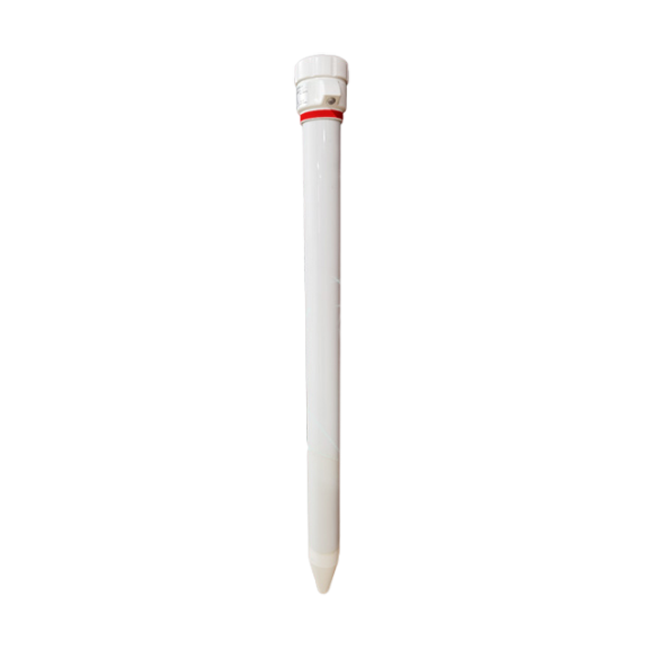 Multi-Depth Soil Sensor RS485
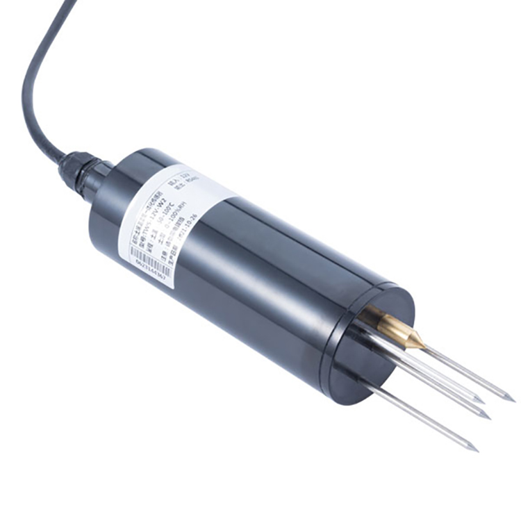 TDR Soil Moisture Sensor
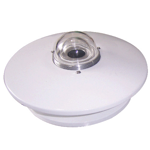 Pyranometer Solar Radiation Sensors
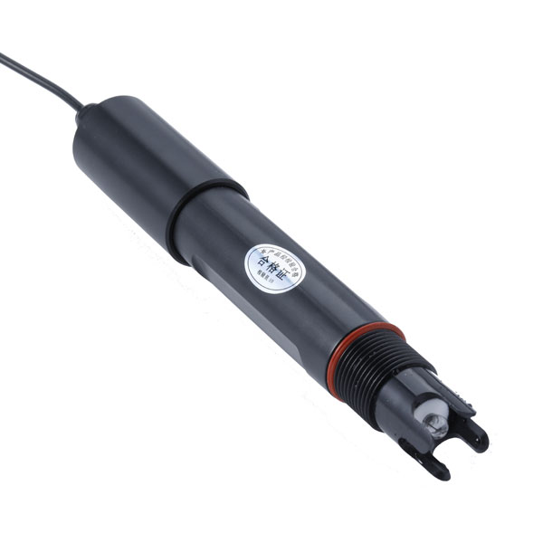 Soil ph sensor
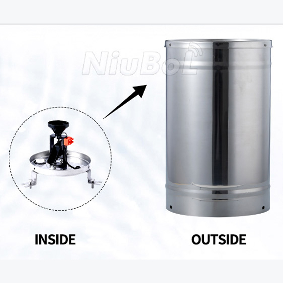 Tipping Bucket Rain Gauge
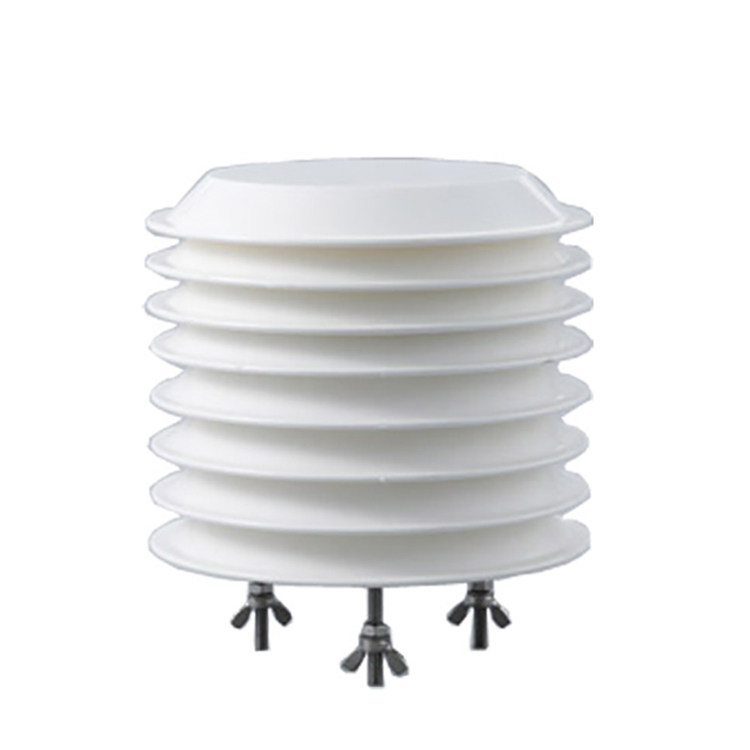 Air Temperature and Humidity Sensor

Screenshot, WhatsApp to identify the QR code
WhatsApp number:+8615367865107
(Click on WhatsApp to copy and add friends)