





— Download —
 Consumer hotline +8618073152920
WhatsApp:+8615367865107
Address:Room 102, District D, Houhu Industrial Park, Yuelu District, Changsha City, Hunan Province, China
All products


Compare NiuBoL tipping bucket and piezoelectric rainfall sensors. Check resolution, daily totals, vibration and Modbus read modes before specifying your monitoring point.
Tel/WhatsApp:+8615367865107
Email:Arvin@niubol.com +Nearly 100 partner companies in more than 75 countries. We are committed to providing high-quality, practical products to meet your needs and help you solve problems. Our products comply with international standards and are certified with ISO, CE and RoHS.Product Details
Quick Answer: Choose between a tipping bucket and a piezoelectric rainfall sensor by the required rainfall record, receiving input and installation conditions. The NiuBoL NBL-W-RS converts collected water into bucket events; the NBL-W-PRS estimates rainfall from raindrop impacts. Their resolution, accuracy conditions and maintenance tasks differ. A 0.01 mm output increment is not, by itself, evidence of more accurate daily totals than a 0.2 mm tipping bucket.

Event detection, daily totals, irrigation suspension, hydrology and research use different intervals and quality controls. State whether accumulation, intensity or both drives the decision.
A farm controller may need a dependable accumulated depth before suspending irrigation. A drainage investigation may need rainfall over short intervals. A long-running station may need continuity with an existing gauge. Those tasks can favor different acquisition and comparison methods even at the same site.
| Parameter | NBL-W-RS tipping bucket, 0.2 mm configuration | NBL-W-PRS piezoelectric sensor |
|---|---|---|
| Measurement | Collected liquid water produces bucket events | Raindrop impacts produce signals used to estimate rainfall |
| Intensity range | 0-4 mm/min | 0-8 mm/min |
| Resolution | 0.2 mm per tip | 0.01 mm reported rainfall increment |
| Specified accuracy | +/-4%, indoor static test at 2 mm/min | +/-4% for daily accumulated rainfall |
| Output choices | Reed-switch pulse, voltage or RS485, as ordered | RS485 Modbus RTU |
| Supply | 5 VDC or 12-24 VDC, according to output configuration | 12-24 VDC |
| Operating temperature | 0-50 degrees C | -40 to 80 degrees C |
| Additional selection details | 200 +/-0.6 mm collector diameter; standard 5 m cable | IP66 housing; average current below 5 mA at 12 V |
These are two defined configurations, not specifications for every rainfall instrument. Other tipping depths need their own conversion and performance limits. The NBL-W-PRS operating temperature does not establish snowfall measurement or a heated all-precipitation capability.
Keep the accuracy conditions with the numbers. A daily accumulated-rainfall statement and a controlled test at one intensity do not provide identical evidence for a short storm peak. If a contract depends on interval intensity, specify that interval and the required comparison before choosing the method.
Water fills one side of a balanced mechanism until it tips and generates an event. The logger converts counts using the configured depth per tip. Blockage, poor level and unsuitable high-intensity response can affect results.
In an idealized example, steady rain at 0.2 mm/h takes one hour to fill an initially empty 0.2 mm bucket to its first tip. The actual first-event delay also depends on water already in the bucket. No tip during a short observation therefore does not establish that no rain has fallen.
One 0.2 mm tip assigned to a one-minute interval corresponds to an interval rate of 12 mm/h. That is an accumulation divided by time, not proof that the rainfall stayed at 12 mm/h throughout the minute. Use an agreed interval or inter-tip method rather than presenting a coarse event count as a continuously resolved intensity trace.
A pulse logger counts bucket events. With the 0.2 mm configuration, 50 accepted tips represent 10 mm. Select a compatible counter input and check that its filtering does not count contact bounce or suppress valid events. A digital gauge reports a scaled rainfall value instead; applying the pulse multiplier again creates a conversion error.
For the NBL-W-RS V4.0 digital configuration, the rainfall conversion uses 0.1 mm per decoded count. The NBL-W-PRS rainfall conversion uses 0.01 mm per count. A decoded value of 200 therefore represents 20.0 mm in the first definition and 2.00 mm in the second. Map the ordered device explicitly rather than copying one rainfall channel into another.
The RS485 versions use Modbus RTU at 9600 baud with 8 data bits and no parity. Match the delivered stop-bit setting. Allow at least 1000 ms between NBL-W-RS V4.0 communications and more than 1000 ms for the NBL-W-PRS configuration.
A logger that accepts reed-switch inputs may not accept an RS485 device without a different input or acquisition module. Conversely, a spare serial port does not turn a pulse gauge into a Modbus instrument. Confirm supply, input type and the selected output together before ordering a replacement.
A piezoelectric surface detects impact from drops and uses signal processing to estimate rainfall. With no tipping bucket, maintenance differs, but wind, drop size and the model algorithm remain part of the measurement method.
Mount the NBL-W-PRS horizontally on a rigid support more than 500 mm above ground, with clear exposure to rainfall. Prefer the upper end of the support rather than a vibrating side arm. Keep it away from machinery vibration and prevent loose cables from striking or shaking the assembly. Shelter, splash and water dripping from an upper instrument can change what reaches the sensing surface.
The 0-8 mm/min range converts to 0-480 mm/h; it is an intensity range, not a maximum daily total. Do not compare it with a daily accumulation value or infer that every short interval has the daily-total accuracy. Evaluate the installation under the rainfall conditions relevant to the project.
The NBL-W-PRS supports accumulated output and a read-and-clear mode. Set one authoritative acquisition path when reading clears the value. If a PLC and a gateway independently read that channel, one may clear rainfall before the other has received it. Share the logger's stored result instead of allowing competing readers to alter the sensor record.
Archive totals before an intentional reset and test power interruption and reconnection. Do not assume every counter survives a restart or resets at the same daily boundary. A zero following a confirmed reset is different from a zero substituted after failed communication.
For a tipping bucket, check the level, clear water path, shipping restraints and received events. Apply a controlled water quantity at an appropriate rate and compare expected depth with the collected record. Pouring rapidly can test overflow or mechanical response instead of the intended calibration condition.
For a piezoelectric sensor, pouring a measured volume onto the surface does not reproduce a known depth of natural rainfall. The device responds to impacts, so drop formation, impact distribution and mounting vibration matter. Use an appropriate rainfall comparison or a supplier-agreed test method rather than transferring the tipping-bucket pour test unchanged.
During a field comparison, align accumulation windows and record cleaning, interruptions and reset events. First compare whole-event totals, then examine interval behavior. Two gauges with similar event totals can distribute that total differently over time, which matters when a drainage model or irrigation rule consumes short intervals.
Do not adjust either instrument to match one isolated storm. Check exposure and the reference arrangement first. If the project changes method at an established station, retain an overlap period and mark the change in the station history so later analysis can identify it.
Inspect funnels, screens, drains, insects, fasteners and level. Use a documented controlled-water test and compare the expected number of tips or accumulated value at the logger.
A tipping bucket needs access to its funnel, filter, drains and moving mechanism. A piezoelectric design removes that mechanism, but the impact surface, rigid mounting and cable restraint still need inspection. Low mechanical servicing demand is not a guarantee that contamination, bird activity or vibration cannot affect the record.
Where visits are difficult, consider which faults the receiving system can reveal and which still need physical inspection. A changing counter proves data is arriving; it does not establish that a blocked collector is catching rain correctly or that an impact surface has an appropriate exposure.
For a quotation, identify the rain variable and interval, expected peak intensity, available input and supply, mounting arrangement and service access. Include logger configuration and the acceptance method in the comparison. A bare sensor price cannot show whether a replacement will work with the existing station.
No. Resolution describes the output increment, while accuracy has its own conditions. Compare accumulated-rainfall performance, interval behavior and installation requirements for the intended duty, not the number of decimal places.
A compatible tipping-bucket pulse version can use that input. The NBL-W-PRS requires RS485 acquisition, so include a suitable logger port or interface in the replacement plan rather than assuming a matching rain variable means a matching electrical signal.
No. A controlled water quantity can exercise a collector and tipping mechanism. A piezoelectric impact surface needs a test or rainfall comparison that represents its measurement principle. Agree the procedure before commissioning.
Collected water must reach the tipping volume. In light rain, that can take a substantial part of the reporting interval. Consider bucket capacity and partial filling before treating a short period without tips as a dry observation.
Only when the selected read behavior permits it. With read-and-clear output, designate one reader and distribute its saved result. Otherwise competing reads can split or remove rainfall from one system's record.
No. Environmental survival or operation is different from measuring frozen precipitation as water equivalent. Specify a suitable all-precipitation arrangement when snow or freezing conditions are part of the required rainfall record.
Keep the configuration, installation position, conversion, reset behavior and change date. An overlap comparison with aligned totals helps distinguish the method change from an actual change in rainfall.
Select a tipping bucket when collected-water events and the available pulse or transmitter interface fit the station. Select a piezoelectric sensor when its impact-based method, rigid mounting and digital acquisition suit the duty. Compare the complete rainfall record and acceptance method. Send NiuBoL the rainfall objective and existing logger details for a compatible configuration.
Prev:10 in 1 Weather Station RS485 Modbus
Next:7-in-1 Soil Multi-Parameter Sensor | RS485 Modbus | NBL-TMC-7
Sensors & Weather Stations Catalog
 Agriculture Sensors and Weather Stations Catalog-NiuBoL.pdf
Weather Stations Catalog-NiuBoL.pdf
Agriculture Sensors Catalog-NiuBoL.pdf
Water Quality Sensor Catalog-NiuBoL.pdf
Related recommendations
 Multi-Depth Soil Sensor RS485
 TDR Soil Moisture Sensor
 Pyranometer Solar Radiation Sensors
 Soil ph sensor
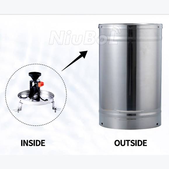 Tipping Bucket Rain Gauge
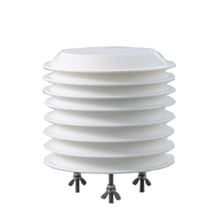 Air Temperature and Humidity Sensor


Screenshot, WhatsApp to identify the QR code
WhatsApp number:+8615367865107
(Click on WhatsApp to copy and add friends)

