





— Download —
 Consumer hotline +8618073152920
WhatsApp:+8615367865107
Address:Room 102, District D, Houhu Industrial Park, Yuelu District, Changsha City, Hunan Province, China
All products

Select a NiuBoL CO2 concentration sensor for greenhouse or ventilation control. Check air sampling, accuracy, response and output compatibility before requesting pricing.
Tel/WhatsApp:+8615367865107
Email:Arvin@niubol.com +Nearly 100 partner companies in more than 75 countries. We are committed to providing high-quality, practical products to meet your needs and help you solve problems. Our products comply with international standards and are certified with ISO, CE and RoHS.Product Details
Quick Answer: The NiuBoL NBL-W-CO2 concentration sensor provides a 0-5000 ppm channel for greenhouse and building-control projects, with RS485 or 4-20mA output and 12-24 VDC supply. Select the sampling location and control purpose together: greenhouse enrichment and occupancy-related ventilation use the same measured gas for different decisions. Its accuracy is +/-(50 ppm + 3% of reading), not 1 ppm simply because the output resolution is 1 ppm.

In occupied buildings, CO2 trends can indicate whether outdoor-air delivery keeps pace with occupancy, but the sensor does not measure every indoor contaminant. In greenhouses, the same channel can inform ventilation and CO2 dosing. Those uses need different setpoints, locations and fail-safe responses.
For greenhouse enrichment, the relevant observation is normally the air reaching the managed crop area, not the concentration at the dosing outlet. Divide the installation by independently managed compartments and identify how vents, circulation and dosing distribute the gas. One point cannot establish uniformity across disconnected or differently ventilated spaces.
For an occupied building, choose whether the sensor represents one room, a zone or a return-air mixture. A return-air reading can conceal a poorly ventilated room within the combined stream. A sensor next to a supply diffuser can instead follow incoming air rather than the conditions of the occupied zone.
Keep the measurement objective on the mounting drawing. Record the relation to people, doors, fans, heaters and dosing equipment so a later relocation does not silently change what the control input represents. More sensors are useful when they resolve meaningful differences; placing several at the same unrepresentative outlet does not solve the sampling problem.
| Item | Specification |
|---|---|
| CO2 measuring range | 0-5000 ppm |
| Accuracy | +/-(50 ppm + 3% of reading) |
| Resolution | 1 ppm |
| Supply | 12-24 VDC |
| Output options | RS485 Modbus RTU or 4-20mA, as ordered |
| Current-output load limit | 250 ohms maximum |
| Standard cable | 2.5 m |
| Operating environment | -10 to 50 degrees C; 0-100% RH |
| Power and weight | 0.2 W; 140 g |
Check expected peaks as well as the normal control target. A channel that reaches its 5000 ppm endpoint cannot quantify a higher concentration from that endpoint alone. Do not specify a wider measuring range by changing the PLC display scale.
The humidity range does not establish resistance to condensation, washdown or agricultural chemicals. Review direct wetting, spray, dirt and housing exposure at the intended point. Keep the sampled air accessible to the sensor while protecting power and signal connections appropriately.
At 800 ppm, the percentage term is 24 ppm and the combined specified error is +/-74 ppm. At 1500 ppm it is +/-95 ppm. These calculations illustrate the fixed-plus-reading expression; they are not proposed crop setpoints or building ventilation limits.
A small difference between two display values can be less meaningful than variation between nearby locations. Before tightening an operating band, compare the measurement tolerance with spatial variation, response time and the time needed for the controlled air to mix.
Use separate switching or modulation rules to prevent a fan or dosing valve from repeatedly reversing around one value. The required separation and delays depend on the process. Do not use a universal deadband derived only from the 1 ppm resolution or add a large software smoothing filter to conceal a poorly located sensor.
A slow or heavily averaged signal can look stable while reporting an earlier condition. Specify the controller's sampling, averaging and freshness checks together. Any alarm or process response should act on a valid, appropriately timed value rather than a plausible number left over from a disconnected device.
Before enabling automatic dosing, verify that the point is not dominated by a local jet and that the intended circulation is operating. Observe normal system changes and compare points within the compartment. A strong difference between the dosing side and the far end calls for an airflow investigation, not simply a higher target.
Use actual ventilation and circulation status where the control design requires it. A valve-open command does not prove gas delivery, and a fan command does not prove air movement. Commission the relevant feedback and inhibit conditions with the installed equipment rather than testing the sensor screen alone.
Test how the controller rejects stale data, a disconnected sensor and an out-of-range result. Automatic enrichment should not continue on the assumption that unavailable input means zero CO2. The ventilation, alarm and shutdown response must follow the site's engineered operating and safety arrangements.
This concentration channel is a process input, not evidence that an installation has a certified gas-safety system. Specify independent protective equipment where the duty requires it. No absence-of-hazard conclusion should be drawn from an unverified, saturated or failed process channel.
Use CO2 trends with occupancy and the operation of outdoor-air equipment. A rise associated with normal occupancy can help investigate ventilation, but it does not identify every cause of a reading or establish a universal airflow rate from concentration alone.
Do not infer acceptable particles, volatile compounds or other pollutants from a low CO2 value. CO2 measurement addresses one gas and can support an appropriately designed ventilation strategy; it is not a complete assessment of indoor air quality.
When comparing rooms, align occupancy periods, door conditions and measurement timing. Check whether the sensors use comparable settings and whether one is exposed to a local source. A difference between a busy room and an empty corridor is not sufficient evidence that either sensor needs calibration.
The NBL-W-CO2 digital configuration uses Modbus RTU at 9600 baud, 8 data bits and no parity, with at least 1000 ms between communications. Match the supplied stop-bit setting and assign the delivered channel definition to the receiver.
For the 0-5000 ppm current version, C = (I - 4) / 16 x 5000, with current in mA and concentration in ppm. The ordered powered-output wiring and the receiver must match. Include the entire current-path load within the 250 ohm limit; a matching 4-20mA label alone does not establish a compatible connection.
Confirm the value at the local controller and again after onward transmission. Check that a gateway does not apply a second conversion to a value already in ppm. Where several controllers require the same measurement, define one consistent acquisition and distribution arrangement instead of allowing conflicting configuration changes.
For a measurement check, colocate a suitable reference in comparable air and allow the instruments to equilibrate. Compare time-aligned observations with their response and averaging settings recorded. Do not force a calibration to an assumed outdoor concentration or another room's reading.
For a control-response check, observe a normal occupancy or greenhouse operating change and verify the resulting controller action. That test can reveal poor location, excessive delay or a reversed response, but it does not replace a defined calibration procedure.
Retain the comparison conditions, output version and any authorized correction with the device record. Before changing a coefficient, investigate dirty openings, wetting, power and receiving configuration. A numerical offset can conceal a sampling or installation problem without correcting it.
A suitable data logger or gateway can store the CO2 channel and the associated equipment states. The broader monitoring diagram below shows optional environmental instruments; it does not imply that the CO2 sensor also measures wind, rainfall or soil conditions.
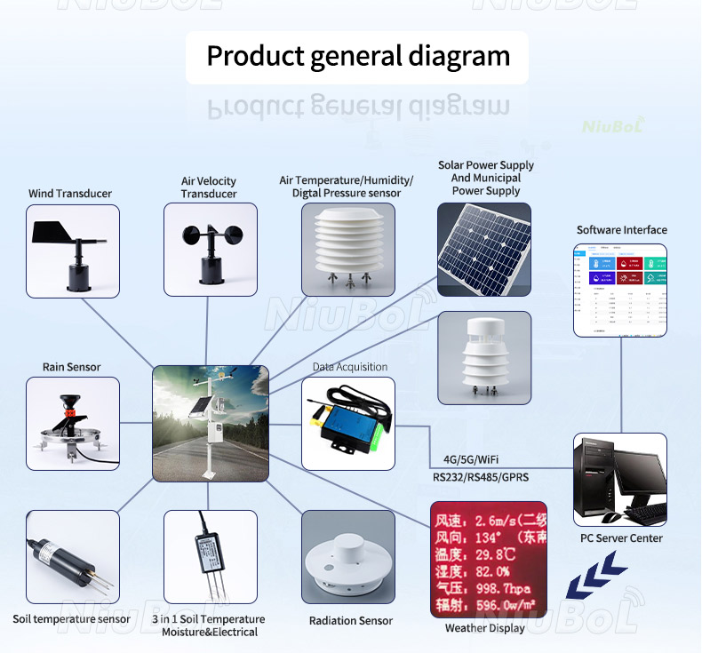
Only if its air sample represents the managed area under the relevant operating conditions. Independently ventilated compartments, localized dosing and persistent gradients can require separate points. Check distribution before assuming one reading represents the entire crop.
It is the result of the sensor's accuracy expression at that reading, not a prescribed control band. The control design also needs spatial variation, response, mixing and actuator behavior. Set and test the operating rules for the actual process.
No. A range endpoint cannot quantify how far above range the actual concentration lies. Specify a suitable instrument when expected peaks exceed the selected span, and define how saturated or invalid readings are handled.
No. Outdoor concentration varies with location and time, and a casual outdoor observation is not a calibration standard. Use a suitable reference and an agreed comparison or calibration method.
Use RS485 when the receiver supports the required Modbus acquisition. Use the current version when the powered output, load and input match. Specify the exact controller interface, not just the desired ppm value.
No. CO2 can support ventilation investigation under defined conditions, but the channel does not measure particles, volatile compounds or every other pollutant. Select additional measurements where those are part of the project objective.
Flag the invalid or stale measurement and use the engineered fallback. In an enrichment application, do not interpret lost input as a genuine zero that calls for continued dosing. Verify recovery and any required operator intervention during commissioning.
Provide normal and peak concentrations, greenhouse or ventilation duty, the area and compartment layout, receiving equipment and output preference. Include power, cable routing, wetting exposure, comparison requirements and any separate protective functions.
Select the CO2 concentration sensor around the air sample and the decision it supports. Match the 0-5000 ppm range, conditional accuracy and ordered interface to the controller, then test measurement and process response separately. Send NiuBoL the airflow layout and control requirements for configuration review.
Sensors & Weather Stations Catalog
 Agriculture Sensors and Weather Stations Catalog-NiuBoL.pdf
Weather Stations Catalog-NiuBoL.pdf
Agriculture Sensors Catalog-NiuBoL.pdf
Water Quality Sensor Catalog-NiuBoL.pdf
Related recommendations
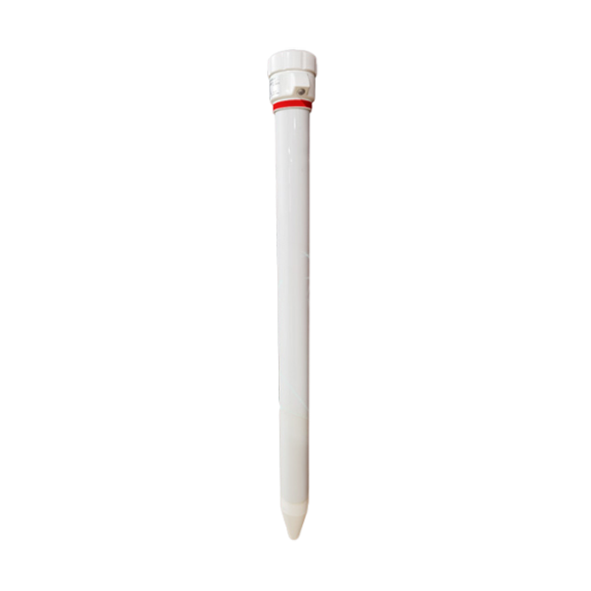 Multi-Depth Soil Sensor RS485
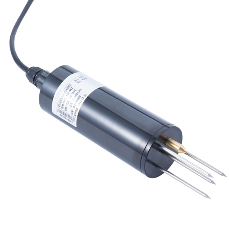 TDR Soil Moisture Sensor
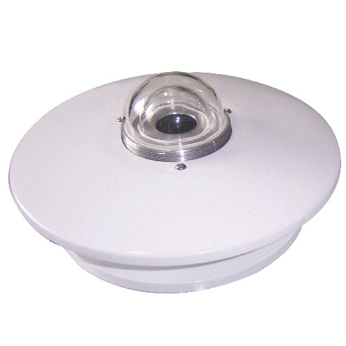 Pyranometer Solar Radiation Sensors
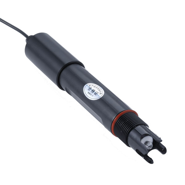 Soil ph sensor
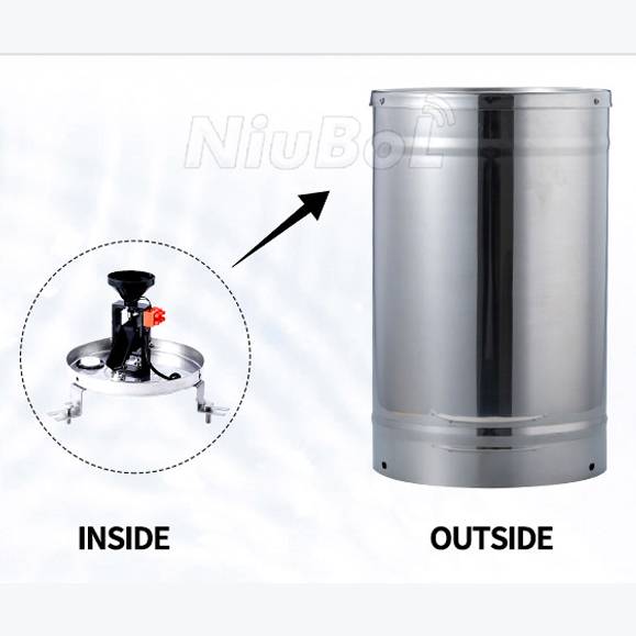 Tipping Bucket Rain Gauge
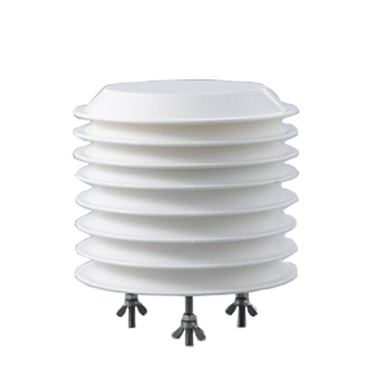 Air Temperature and Humidity Sensor


Screenshot, WhatsApp to identify the QR code
WhatsApp number:+8615367865107
(Click on WhatsApp to copy and add friends)

