





— Download —
 Consumer hotline +8618073152920
WhatsApp:+8615367865107
Address:Room 102, District D, Houhu Industrial Park, Yuelu District, Changsha City, Hunan Province, China
All products


Design a NiuBoL soil moisture-based irrigation system with RS485 inputs, valve scheduling and bounded cycles. Review pump capacity and acceptance tests before specifying.
Tel/WhatsApp:+8615367865107
Email:Arvin@niubol.com +Nearly 100 partner companies in more than 75 countries. We are committed to providing high-quality, practical products to meet your needs and help you solve problems. Our products comply with international standards and are certified with ISO, CE and RoHS.Product Details
Quick Answer: A soil moisture-based irrigation system needs a controller between the probes and the valves. The probes generate measurements; the controller decides which zone may run, checks shared pump capacity and limits each cycle. For a multi-zone project, specify how requests are queued, how water delivery is confirmed and how operation recovers after a power or communication interruption before purchasing the automation package.

The measurement path is soil probe to PLC, RTU or irrigation controller, followed by recording and any remote supervision. The actuation path is the controller through a suitable output stage to the valve and pump equipment. An RS485 soil sensor does not supply the power or switching function needed to operate a solenoid.
One compatible measurement input is the NiuBoL NBL-S-THR. Its moisture and temperature values can support a zone request, but the controller and hydraulic equipment remain separately specified components. For detailed probe wiring and conversion, use the NBL-S-THR integration information rather than assuming a sensor-only order includes the complete control system.
| Reference input specification | NBL-S-THR |
|---|---|
| Moisture | 0-100%; 0.1% resolution; stated accuracy +/-3% |
| Temperature | -50 to 100 degrees C; 0.1 degree C resolution; +/-0.5 degree C accuracy |
| Power supply / consumption | 12-24 VDC; approximately 0.3 W |
| Ordered output | RS485 Modbus RTU, 4-20 mA or 0-5 V |
| Operating temperature / probe protection | -40 to 80 degrees C; IP68 |
| Cable and field connections | Specify the required jacket, length, termination and separate joint protection |
These are probe specifications, not ratings for a pump panel, valve supply or complete station. Size those components from the installed loads and local electrical requirements. The controller must support the ordered sensor interface and the required number of independently switched zones.
Group points by valve, soil texture, slope, crop and irrigation method. One convenient probe should not control several unlike zones. The location must answer a defined question: when to start, when to stop, whether water reached the roots or whether drainage passed below them.
For each zone, identify the measurement used to request irrigation, its current validity and the operating window. A valid dry condition can create a request while the scheduler decides whether the zone is permitted to run. This prevents every dry probe from opening its valve simultaneously when the shared supply cannot support that demand.
Set the request and release conditions from an agronomically valid soil-water method and field observations. Hysteresis prevents repeated requests around one threshold. The decision also needs the last sample time and whether a previous cycle is still soaking into the soil. A new low reading does not necessarily justify another immediate cycle.
Identify the combinations of zones that the supply can operate at their required pressure. Adding zone flow rates is a useful first check, but the available flow must be assessed at the operating pressure and with the installed pipe losses. A pump's nominal maximum flow is not a guarantee that every combination will irrigate correctly.
As an illustrative scheduling check, suppose two zones require 12 and 10 L/min, while the usable supply at the required operating pressure is 18 L/min. Their combined 22 L/min demand exceeds that supply, so they should not be scheduled together on that basis. These numbers are a design example, not NiuBoL equipment ratings or a field recommendation.
Define how simultaneous requests are prioritized: for example, by an approved zone priority and waiting time. Retain pending requests when another zone starts, but recheck their soil condition and permissions before execution. A request may no longer be appropriate after rain, a manual operation or a long delay.
| Cycle state | Controller behavior to specify |
|---|---|
| Waiting | Evaluate valid zone requests, operating windows and shared capacity without energizing the valve. |
| Starting | Apply the approved pump/valve sequence and verify the required delivery feedback. |
| Irrigating | Track elapsed time or delivered volume, soil feedback and hydraulic conditions. |
| Soaking | Keep the valve closed for the defined redistribution period before permitting another request from that zone. |
| Inhibited or faulted | Apply the agreed stop or fallback action and show why automatic operation is unavailable. |
Specify maximum runtime and any volume limit independently of the moisture stop condition. An incorrectly placed probe may never reach the expected value while water continues elsewhere. Minimum runtime can reduce short cycling, but it must never override a hydraulic protective stop or extend operation beyond the configured maximum.
Use observed wetting and redistribution behavior to set the relevant delays. Keep sensor sampling, controller evaluation and upload intervals separate: a more frequent dashboard refresh does not make water move faster through soil. The local control sequence should remain understandable when the remote screen is unavailable.
A command confirms what the controller asked the output to do. Flow or another appropriate delivery check helps establish whether the hydraulic system responded. A closed command does not prove a sticking valve has stopped water, just as an open command does not prove a blocked emitter is delivering it.
| Observed condition | Investigation and control question |
|---|---|
| Open command without expected delivery | Check supply, valve actuation, pressure and blockage; use a bounded start-verification procedure. |
| Delivery persists after a close command | Investigate valve closure or unintended flow and invoke the specified hydraulic response. |
| Normal delivery without a soil response | Check wetting delay, location, contact and the actual irrigated area rather than extending watering indefinitely. |
| Several zones request irrigation together | Apply the approved capacity limit and priority sequence instead of energizing all outputs. |
Record commands and delivery observations on the same time reference. Where one flow meter serves several zones, its interpretation depends on which valves are running. An aggregate flow value cannot identify a particular failed branch without the relevant operating context.
Stale or missing values should raise a fault and move the zone to a documented safe schedule or operator review. Do not treat failed communication as zero moisture. Store the last valid timestamp and sensor status with the reading.
Loss of the remote connection and loss of a valid local soil measurement are different faults. If operation must continue without the server, specify a controller with the required local schedule and limits. If local sensing becomes unavailable, use the owner's agreed fallback; do not let a default zero create a permanent dry-soil request.
On restart, check actual output states and whether a previous watering cycle was interrupted. Do not automatically repeat its full duration or assume it was completed. The approved recovery can require operator review or a bounded remaining cycle, but the choice needs to be explicit and tested.
Remote commands also need an expiry and a clear acknowledgement method where that function is used. A delayed start request should not open a valve hours after the intended window simply because the connection returned. Reconcile local manual operation with the server record rather than blindly replaying stored commands.
Begin with one zone in supervised operation. Verify that its identified probe and controller input correspond to the valve that waters it. Observe the start sequence, actual delivery, wetting response, stop and redistribution. Then test the permitted shared-zone combinations and verify that excess simultaneous demand is queued.
Test faults using approved electrical or software simulation where practical, without damaging sensors or running a pump under unsafe conditions. Demonstrate stale data, a refused zone request, maximum-runtime termination and reconnection handling. Protective tests and pump operation must follow the site's approved commissioning procedure.
The acceptance record should show the expected and observed result for each event. Include configuration values and software revision so a later change to a timeout, zone priority or output assignment can be assessed. A screen showing plausible soil percentages does not establish that the valves run in the right order.
Give NiuBoL or the system integrator the zone list, soil input types, existing controller, valve loads, supply limitations and remote-operation requirements. Identify who supplies the output panel, delivery feedback, power and commissioning. Request the proposed interfaces and responsibilities with the quotation, not after field cabling is complete.
A soil moisture-based irrigation system can use NiuBoL probes and compatible acquisition equipment without requiring every project to have the same architecture. The useful comparison is whether each proposal can execute and demonstrate the required zone sequence, not whether it contains the largest number of sensors or dashboard functions.
The rectangular multi-pin probe below is a different sensing assembly from the cylindrical NBL-S-THR. If an alternative multi-parameter probe is selected, specify its own channels, electrical version and driver. Do not apply the NBL-S-THR input map merely because both devices connect to the same irrigation controller.
The NBL-S-THR provides a measurement output, not a valve power stage. Specify a compatible controller and suitable switching hardware. Their ratings and control logic must match the actual valve and pump equipment.
Create requests and schedule the permitted combinations against supply capacity at the required operating pressure. Use an agreed priority or queue, then recheck each request before it runs. Do not assume the pump can serve all requested zones concurrently.
No. A minimum runtime is an operating preference for avoiding short cycles. Hydraulic protective conditions and the configured maximum limits must take priority. Test that precedence during commissioning.
Water continues to redistribute after delivery stops. A defined soak state prevents the controller from immediately requesting another cycle because the selected depth has not yet reached its response. Set its duration from local behavior rather than a universal timer.
Reconcile actual valve/output states and the interrupted cycle before resuming. Use the approved recovery rule rather than automatically repeating the complete watering period. Record whether operator review or a bounded continuation is required.
No. Local measurements and control may remain available while remote reporting is offline. Conversely, a reachable dashboard can display an old sensor value. Define and test the two conditions separately.
Only according to an explicit command-validity rule. Where remote starts are used, define expiry, acknowledgement and interaction with manual operation. Do not treat every queued message as a currently authorized watering request.
Demonstrate correct zone identity, delivery, permitted concurrency, bounded runtime, soak behavior and fault recovery. Retain the tested configuration and results. Sensor communication alone is not evidence that the hydraulic sequence operates correctly.
Build a soil moisture-based irrigation system around valid zone requests, available hydraulic capacity and observable cycle states. NiuBoL soil probes provide the input measurements; the specified controller and output equipment must turn them into bounded, testable operation. Define scheduling and recovery before purchase so the completed project can be accepted by what it does in the field.
Sensors & Weather Stations Catalog
 Agriculture Sensors and Weather Stations Catalog-NiuBoL.pdf
Weather Stations Catalog-NiuBoL.pdf
Agriculture Sensors Catalog-NiuBoL.pdf
Water Quality Sensor Catalog-NiuBoL.pdf
Related recommendations
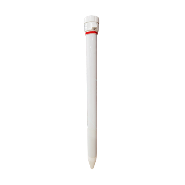 Multi-Depth Soil Sensor RS485
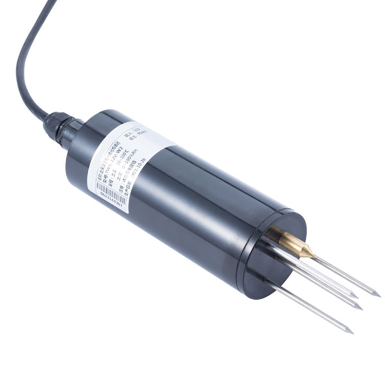 TDR Soil Moisture Sensor
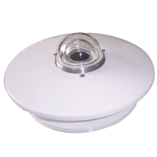 Pyranometer Solar Radiation Sensors
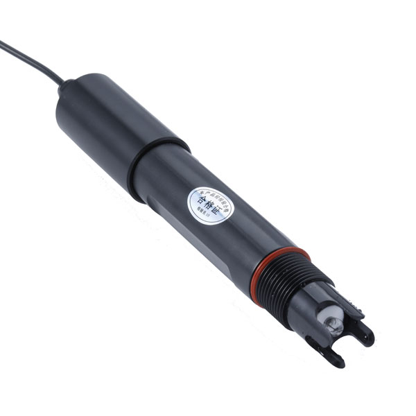 Soil ph sensor
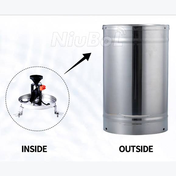 Tipping Bucket Rain Gauge
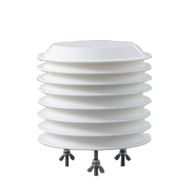 Air Temperature and Humidity Sensor


Screenshot, WhatsApp to identify the QR code
WhatsApp number:+8615367865107
(Click on WhatsApp to copy and add friends)

