





— Products —
 Consumer hotline +8618073152920
WhatsApp:+8615367865107
Address:Room 102, District D, Houhu Industrial Park, Yuelu District, Changsha City, Hunan Province, China
Level Sensors

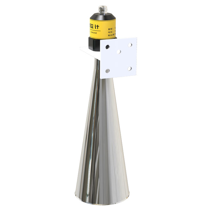
NiuBoL radar water level sensor uses 77–79 GHz FMCW technology with 0.1–65 m range, 6° narrow beam, ±1 mm specified accuracy and RS485 Modbus for hydrology and flood monitoring.
Tel/WhatsApp:+8615367865107
Email:Arvin@niubol.com +Nearly 100 partner companies in more than 75 countries. We are committed to providing high-quality, practical products to meet your needs and help you solve problems. Our products comply with international standards and are certified with ISO, CE and RoHS.Product Details
The NiuBoL radar water level sensor is a non-contact level measurement instrument designed for continuous monitoring of rivers, reservoirs, irrigation channels, drainage systems, flood-prone areas and other hydrological applications.
The sensor uses 77–79 GHz FMCW millimeter-wave radar to measure the distance between the radar antenna and the water surface. The standard configuration provides a 0.1–65 m measurement range, a 6° narrow beam angle, an approximately 10 cm blind zone and specified measurement accuracy of ±1 mm under defined measurement conditions.
With RS485 Modbus RTU, DC 10–30V power supply, low power consumption and IP67 protection, the sensor can connect to compatible RTUs, PLCs, data loggers and IoT gateways for automatic water-level acquisition and remote hydrological monitoring.
| Specification | Value |
| Product Type | Non-Contact Radar Water Level Sensor |
| Measurement Principle | FMCW Millimeter-Wave Radar |
| Operating Frequency | 77–79 GHz |
| Standard Measurement Range | 0.1–65 m |
| Extended Range | Up to 70 m available depending on configuration and project conditions |
| Specified Accuracy | ±1 mm under specified measurement conditions |
| Beam Angle | 6° |
| Blind Zone | Approx. 0.1 m |
| Communication | RS485 |
| Protocol | Modbus RTU |
| Power Supply | DC 10–30V |
| Power Consumption | <0.2 W |
| Operating Temperature | -40 to +60°C |
| Operating Humidity | 0–95% RH, non-condensing |
| Protection Rating | IP67 |
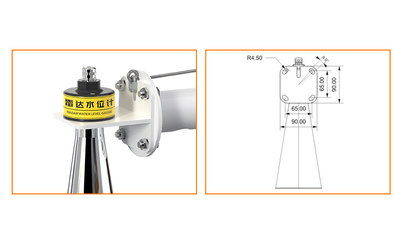
The radar water level sensor uses FMCW, or Frequency Modulated Continuous Wave, technology. The antenna transmits a high-frequency electromagnetic signal in the 77–79 GHz band toward the water surface while continuously varying the transmitted frequency.
The water surface reflects part of the radar energy back toward the sensor. The internal electronics compare the transmitted signal with the received echo and use the frequency difference to calculate the distance between the radar antenna and the water surface.
Because the measurement is non-contact, the sensing element does not need to be submerged in the water. This reduces direct exposure to sediment, floating debris, water-borne contamination and mechanical loads caused by flowing water.
The radar directly measures the distance between the radar reference point and the water surface. Water-level height, water depth or water-level elevation is then calculated using a known installation reference.
Water Level Height = Reference Height − Radar-to-Water Distance
For example, if the radar reference point is installed 10.0 m above the selected zero-level reference and the measured distance to the water surface is 4.2 m, the calculated water level is 5.8 m relative to that reference.
For river, reservoir and flood-monitoring projects, the installation reference should be surveyed and documented carefully so changes in radar distance can be converted into meaningful water-level data.
| Feature | Practical Value |
| 77–79 GHz Operating Frequency | Supports compact antenna design, narrow-beam measurement and high-resolution distance detection |
| 6° Narrow Beam | Helps reduce unwanted echoes from channel walls, bridge structures and nearby objects |
| Small Blind Zone | Allows measurement relatively close to the radar installation point |
| Non-Contact Measurement | No sensing probe is submerged in the river, reservoir or channel |
| Low Power Consumption | Suitable for remote solar-powered monitoring systems when the complete station is correctly sized |
| RS485 Modbus | Supports integration with compatible RTUs, data loggers, PLCs and IoT gateways |
The radar measurement cone becomes wider as the distance between the sensor and the water surface increases. Although this sensor uses a narrow 6° beam, nearby structures still need to be considered during installation.
For preliminary installation planning, the approximate beam diameter can be estimated from the 6° full beam angle:
Beam Diameter ≈ 2 × Distance × tan(3°)
| Radar-to-Water Distance | Approximate Beam Diameter |
| 5 m | Approx. 0.52 m |
| 10 m | Approx. 1.05 m |
| 20 m | Approx. 2.10 m |
| 40 m | Approx. 4.19 m |
| 60 m | Approx. 6.29 m |
These values are geometric estimates for installation planning rather than guaranteed effective measurement-area limits. Actual radar performance also depends on the water surface, mounting orientation, surrounding structures and echo conditions.
The radar sensor combines DC power and RS485 communication in the field cable. The standard product image shows the sensor dimensions, cable structure and electrical connection information.
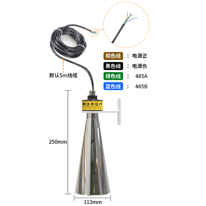
| Connection | Function |
| Power + | DC 10–30V Positive |
| Power − | Power Negative / Ground |
| RS485 A | RS485 Communication A |
| RS485 B | RS485 Communication B |
Use the wire identification supplied with the actual sensor as the final wiring reference because cable colors or connector configurations may differ for customized orders.
The RS485 water level sensor can connect to compatible RTUs, PLCs, data loggers and IoT gateways for continuous data acquisition.
Radar Water Level Sensor → RS485 Modbus → RTU / Data Logger / PLC → 4G / Ethernet → Cloud Platform / SCADA / Private Server
The radar sensor itself provides local water-level measurement data through RS485. Cellular communication, Ethernet, Wi-Fi, MQTT, HTTP, cloud storage or private-server transmission requires a compatible data logger, RTU or IoT gateway.
When several RS485 devices share one communication bus, each instrument should use a unique device address. Power capacity, baud rate, polling interval, cable topology and termination should also be considered when designing the network.
A complete remote water-level monitoring station can include the radar sensor, mounting pole or cross arm, RTU or data logger, protective enclosure, communication antenna, solar panel, battery and lightning-protection components.

Solar-panel and battery capacity should be calculated from the complete station load, including the radar sensor, data logger, cellular communication equipment and any additional rainfall or environmental sensors. Sampling interval, upload frequency and required battery autonomy should also be considered.
Install the radar above the water surface with the antenna directed toward a representative measurement area. The supporting structure should be rigid, and the radar beam should remain clear of unnecessary obstacles throughout the expected water-level range.
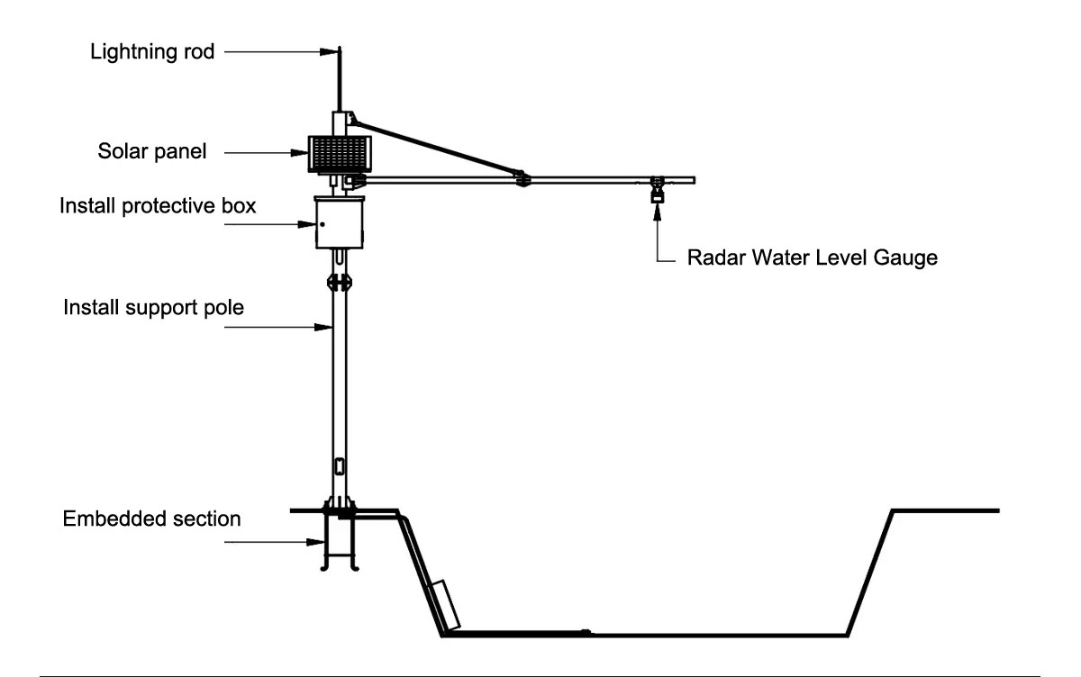
| Installation Item | Recommendation |
| Sensor Orientation | Aim the radar toward the representative water surface and avoid unnecessary tilt. |
| Blind Zone | Keep the highest expected water surface outside the approximately 0.1 m blind zone. |
| Beam Clearance | Keep bridge beams, channel walls, pipes, vegetation and other fixed objects outside the main radar measurement cone where practical. |
| Mounting Structure | Use a rigid bracket or cross arm that minimizes movement and vibration in strong wind. |
| Reference Height | Measure and document the installation reference elevation when absolute water level or water depth is required. |
| Cable Protection | Protect cables and field joints from mechanical damage, UV exposure and water ingress. |
| Commissioning | Compare the initial radar measurement with a known reference distance or manual water-level reading before normal operation. |
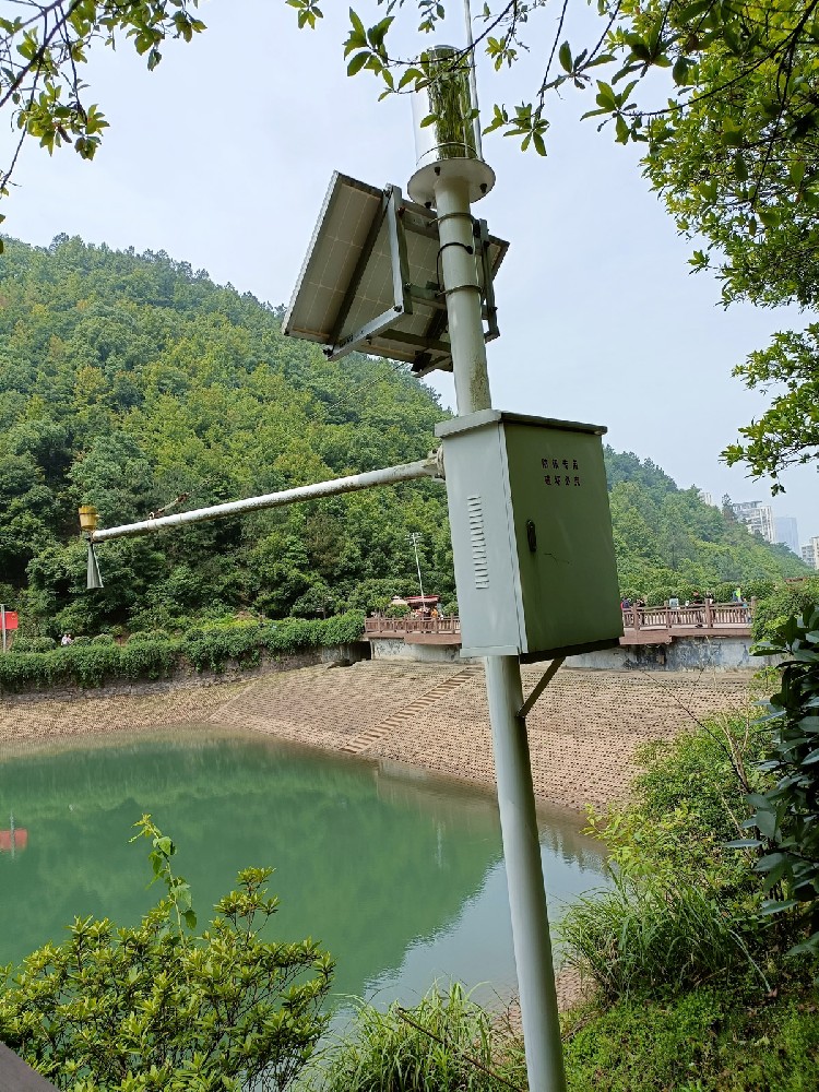
For reservoirs and open-water monitoring, the radar can be installed above the water surface without requiring a submerged pressure probe.
| Selection Item | Radar Water Level Sensor | Submersible Level Sensor |
| Measurement Principle | Non-Contact Radar | Hydrostatic Pressure |
| Contact with Water | No | Yes |
| Sediment Exposure | Sensor remains above the water surface | Submerged probe can be affected by installation position and sediment accumulation |
| Liquid Density | Not used for radar distance measurement | Hydrostatic conversion depends on liquid density |
| Typical Selection | Rivers, reservoirs, channels and non-contact outdoor monitoring | Wells, tanks and submerged level measurement |
For applications where a submerged hydrostatic probe is preferred, see the submersible level transmitter range.
Radar and ultrasonic sensors both provide non-contact level measurement, but they use different physical principles and respond differently to atmospheric and installation conditions.
| Selection Item | Millimeter-Wave Radar | Ultrasonic |
| Measurement Signal | Electromagnetic Wave | Acoustic Wave |
| Air Temperature Effect | Distance measurement is not based on the speed of sound in air | Sound velocity changes with atmospheric temperature and may require compensation |
| Beam Angle | 6° for this configuration | Depends on the ultrasonic transducer design |
| Typical Selection | Long-range hydrological monitoring and sites requiring a narrow measurement beam | General non-contact level measurement where ultrasonic conditions are suitable |
Millimeter-wave radar is well suited to outdoor hydrological monitoring, but field performance still depends on installation geometry, water-surface conditions and the surrounding environment.
| Condition | Consideration |
| Heavy Rain | Radar remains suitable for outdoor rainfall conditions, but severe weather can increase measurement noise and should be considered during commissioning and data filtering. |
| Strong Waves | Rapidly changing or highly inclined water surfaces can increase short-term variation in the measured distance. |
| Foam | Heavy foam can change the effective reflecting surface and should be evaluated for the specific application. |
| Condensation / Dirt | Inspect the antenna surface where installations experience heavy dust, insects, oil mist or persistent condensation. |
| Nearby Structures | Objects inside the radar beam can create unwanted echoes and are one of the most important installation considerations. |
| Mounting Movement | Movement or vibration of the support structure can appear as changes in measured distance. |
River monitoring is one of the main applications for non-contact radar because the sensor can remain above flowing water while continuously measuring changes in the water-surface position.
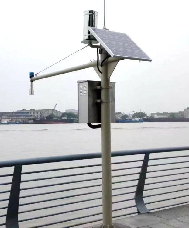
This non-contact water level sensor is suitable for projects where continuous water-level monitoring is required and direct immersion of the sensing element is undesirable.
River Water Level • Reservoir Monitoring • Flood Warning • Urban Waterlogging
Irrigation Channels • Hydrological Stations • Drainage Channels • Remote Water Monitoring
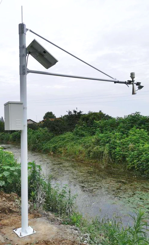
For irrigation channels and drainage systems, the installation point should be selected so that the radar beam remains clear of channel walls, vegetation and structural obstructions throughout the expected water-level range.
| Selection Item | Information to Provide |
| Maximum Distance | Maximum distance from the radar installation point to the lowest expected water surface |
| Highest Water Level | Minimum radar-to-water distance during floods, high tide or full-reservoir conditions |
| Installation Structure | Bridge, riverbank pole, cross arm, culvert, reservoir structure or other mounting point |
| Available Clearance | Channel width and nearby structures used to evaluate the 6° radar beam path |
| Power Supply | Available DC power or required solar and battery system |
| Communication | Local RS485 only or remote 4G / Ethernet communication through an RTU or gateway |
| Server / Platform | Cloud platform, SCADA, MQTT broker, API or private-server requirement |
| Additional Sensors | Rainfall, surface velocity, weather or other hydrological parameters required at the same station |
| Quantity | Sample, pilot site or multi-station project |
A1. It directly measures the distance between the radar antenna and the water surface. Water-level height or elevation is calculated from that distance using the known installation reference.
A2. The standard configuration on this page provides a 0.1–65 m measurement range. Extended range configurations up to 70 m may be available depending on project requirements.
A3. The sensor operates in the 77–79 GHz FMCW millimeter-wave band.
A4. The specified beam angle is 6°. The beam becomes wider as the measurement distance increases, so installation clearance should be checked before mounting.
A5. Yes. The sensor provides RS485 Modbus communication for integration with compatible RTUs, PLCs, data loggers and gateways.
A6. Millimeter-wave radar is suitable for outdoor hydrological monitoring and normally remains operational during rainfall. Severe rain and highly disturbed water surfaces can still increase measurement noise, so field installation and filtering should be validated for the site.
A7. Yes. Non-contact radar can be useful where direct probe contact with wastewater is undesirable. Foam, vapor, condensation, surrounding structures and the reflective condition of the liquid surface should still be considered.
A8. It generally requires less water-contact maintenance than a submerged probe because the sensor remains above the water. The antenna surface, mounting structure, cable, connectors and reference position should still be inspected periodically.
A9. Yes. Connect the RS485 radar sensor to a compatible 4G RTU or IoT gateway. Cellular communication is not built into the standard radar sensor itself.
A10. Yes. Its low power consumption makes it suitable for solar-powered remote stations. Solar-panel and battery capacity should be calculated from the complete station load, transmission interval and required backup duration.
A11. No. ±1 mm is the specified sensor accuracy under defined measurement conditions. Actual field performance depends on measurement distance, installation geometry, water-surface conditions, unwanted echoes and environmental conditions.
A12. Provide the maximum radar-to-water distance, highest and lowest expected water levels, installation structure, channel or reservoir dimensions, quantity, cable requirement, available power supply and whether remote communication or a complete monitoring station is required.
For model selection and quotation, provide the maximum radar-to-water distance, highest and lowest expected water levels, installation structure, available beam clearance, quantity, required cable length and power supply.
For remote hydrological monitoring projects, also specify whether you require an RTU, 4G communication, rainfall sensor, surface velocity sensor, solar power system, protective enclosure, cloud platform, SCADA integration or private-server data transmission.
Prev:Doppler Velocity Meter for Open Channels, Rivers, and Non-Full Pipe Metering
Next:NBL-L-SMP4603 Submersible Level Transmitter Sensor 4-20mA
Sensors & Weather Stations Catalog
 Agriculture Sensors and Weather Stations Catalog-NiuBoL.pdf
Weather Stations Catalog-NiuBoL.pdf
Agriculture Sensors Catalog-NiuBoL.pdf
Water Quality Sensor Catalog-NiuBoL.pdf
Related recommendations
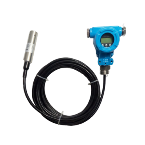 NBL-L-SMP4601 Split-Type Level Transmitter with Real-Time Level Display Output 4-20mA
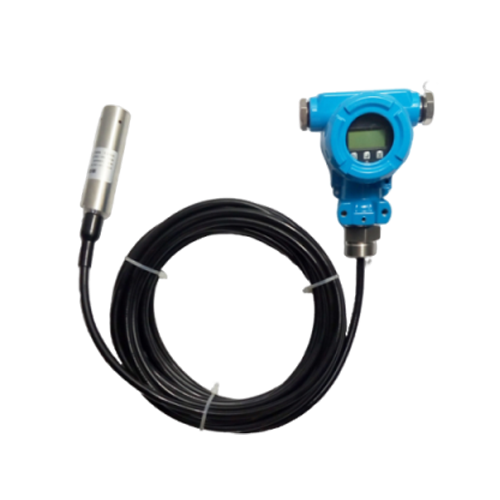 NBL-L-SMP4631 Series RS485/HART/Explosion-Proof Intelligent Split-Type Level Transmitter Sensor
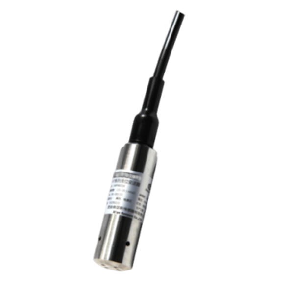 NBL-L-SMP4603 Submersible Level Transmitter Sensor 4-20mA
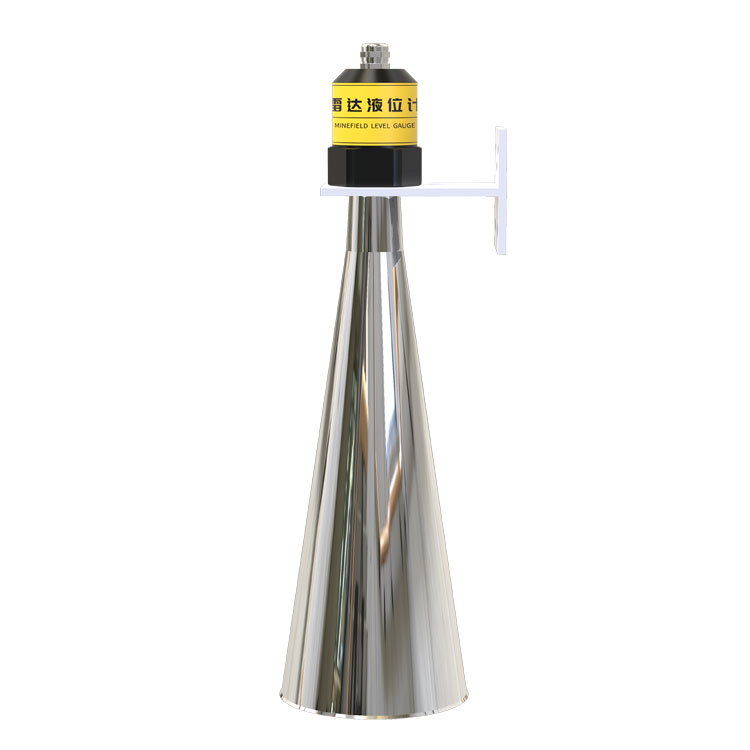 Non-Contact Radar Water Level Sensor RS485 Modbus FMCW | NiuBoL
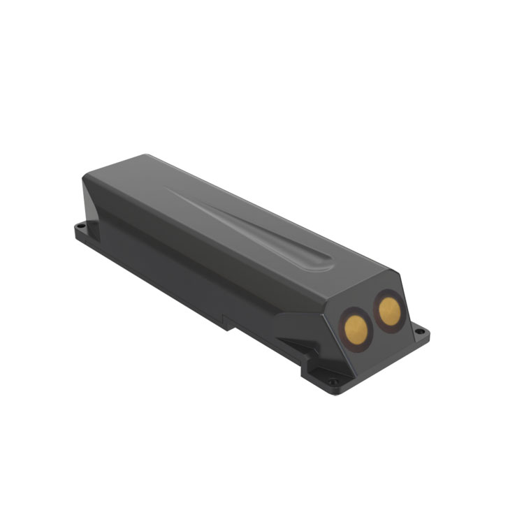 Doppler Velocity Meter for Open Channels, Rivers, and Non-Full Pipe Metering
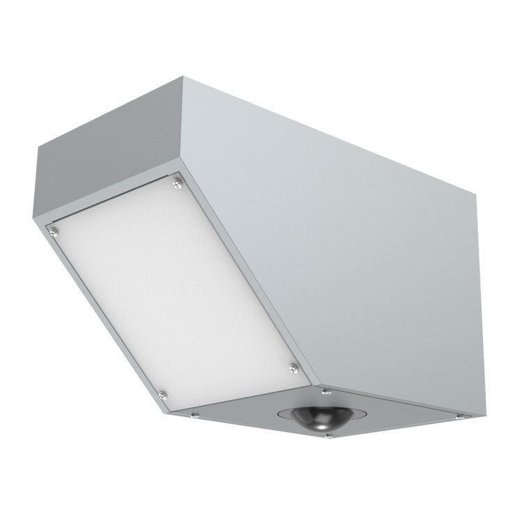 Non-Contact Radar Flowmeter Sensor: All-Weather Flow Monitoring Solution for Smart Water Conservancy


Screenshot, WhatsApp to identify the QR code
WhatsApp number:+8615367865107
(Click on WhatsApp to copy and add friends)

