





— Download —
 Consumer hotline +8618073152920
WhatsApp:+8615367865107
Address:Room 102, District D, Houhu Industrial Park, Yuelu District, Changsha City, Hunan Province, China
All products

Check NiuBoL soil moisture and temperature sensor integration with PLCs and data loggers. Compare analog scaling and Modbus channel checks before ordering your system.
Tel/WhatsApp:+8615367865107
Email:Arvin@niubol.com +Nearly 100 partner companies in more than 75 countries. We are committed to providing high-quality, practical products to meet your needs and help you solve problems. Our products comply with international standards and are certified with ISO, CE and RoHS.Product Details
Quick Answer: NBL-S-THR soil moisture and temperature sensor integration requires two named measurements and the correct ordered output version. Use separate moisture and temperature inputs for analog versions, or decode the temperature word followed by moisture on RS485 Modbus RTU. Apply each channel's own conversion and reject invalid data before passing values to irrigation logic or a remote platform.
The product family offers RS485, 4-20mA and 0-5V. Confirm the ordered output in the purchase order and wiring schedule. Do not assume every unit provides all outputs simultaneously.
On an analog version, moisture and temperature are separate signals even though they share one probe body. Allocate the appropriate receiving inputs and check their common-reference and isolation arrangements. One input cannot acquire both values simply because the sensor cable contains both outputs.
The RS485 version puts both measurements on the communication pair, so channel identity is established by register position rather than separate signal terminals. The PLC, RTU or data logger must support the matching driver and serial configuration. A device with a socket marked RS485 is not necessarily already programmed to interpret this probe.
| Item | NBL-S-THR specification | Integration requirement |
|---|---|---|
| Moisture span / resolution | 0-100% / 0.1% | Keep moisture separate from air relative humidity. |
| Temperature span / resolution | -50 to 100 degrees C / 0.1 degree C | Apply the offset as well as the span on analog inputs. |
| Accuracy | Moisture +/-3%; temperature +/-0.5 degrees C | Use independent acceptance checks for the two quantities. |
| Power supply / consumption | 12-24 VDC / approximately 0.3 W | Provide external power; verify the voltage at the sensor. |
| Output choices | RS485 Modbus RTU, 4-20 mA or 0-5 V | Order one defined version and match the receiving circuit. |
| Analog load limits | Current: up to 250 ohms; voltage: at least 1 kohm | Check input impedance and the full connected arrangement. |
| Operating limits | -40 to 80 degrees C | Do not interpret the temperature span as the assembly operating range. |
| Probe protection | IP68 | Specify suitable field joints and protect exposed transitions. |
| Cable jacket and supplied length | Confirm with the ordered version | Resolve the actual cable route before approving the installation. |
The current-output arrangement uses external power and signal connections; it is not a self-powered two-wire loop instrument. Do not assume a PLC loop supply can replace the indicated wiring. Compare the receiver's active or passive input requirements with the actual transmitter circuit before energizing it.
| Lead | Analog version function | RS485 version function |
|---|---|---|
| Red | Supply positive | Supply positive |
| Black or green | Supply negative / circuit reference | Supply negative |
| Yellow | Soil temperature signal | RS485 A |
| Blue | Soil moisture signal | RS485 B |
Confirm the delivered cable identification before connection, particularly where a preterminated harness or junction box is involved. Isolate power while changing wiring. The same lead color has a different function on an analog and digital version; yellow is not always a temperature signal across the family.
For 0-5 V acquisition, a shared reference error can change the measured signal. For current acquisition, check the specified load and the receiver arrangement rather than adding an arbitrary resistor. If an external shunt is used, include it in the circuit calculation and verify both analog channels before interpreting the soil readings.
For the 4-20 mA version, let I be the measured current in mA. Moisture R = (I - 4) / 16 x 100%, while temperature T = (I - 4) / 16 x 150 - 50 degrees C. The temperature offset is essential: its lower endpoint is -50 degrees C, not zero.
For the 0-5 V version, let V be the measured voltage in volts. Moisture R = V / 5 x 100%, while temperature T = V / 5 x 150 - 50 degrees C. These are conversions for the specified spans, not permission to extend the instrument's operating limits.
| Electrical test value | Moisture channel result | Temperature channel result |
|---|---|---|
| 4 mA or 0 V | 0% | -50 degrees C |
| 12 mA or 2.5 V | 50% | 25 degrees C |
| 20 mA or 5 V | 100% | 100 degrees C |
The table is an electrical scale test. It does not describe simultaneous real soil conditions or require heating the probe to an endpoint. A suitable signal simulator can check the receiving scale without exposing the sensor beyond its operating limit. Use the correct test connection and equipment for the input circuit.
Check a midpoint and endpoints in the receiving software. If 12 mA becomes 75 degrees C, the -50 degree offset has probably been omitted. If a voltage midpoint appears near 2.5 rather than 50% or 25 degrees C, the application may be displaying the raw input without the intended conversion.

For the matching NBL-S-THR configuration, read function 03 from zero-based start address 0x0000 with a count of two registers. The first word is soil temperature and the second is soil moisture. Divide valid decoded measurements by ten to obtain the one-decimal values.
| Register / condition | Meaning | Receiver action |
|---|---|---|
| 0x0000 | Soil temperature | Apply the confirmed signed-value convention and divide by ten. |
| 0x0001 | Soil moisture | Divide a valid value by ten and label it as moisture percent. |
| 0x7FFF in either measurement word | Invalid or missing measurement | Flag unavailable before applying engineering conversion. |
| Example words 0x00B4 and 0x0110 | Decimal 180 and 272 | Temperature 18.0 degrees C and moisture 27.2%. |
Do not divide 0x7FFF by ten and report 3276.7 as a genuine observation. Reject that marker first. Distinguish it from a timeout, which means no valid reply arrived, and from a valid zero measurement. Those conditions require different status handling even if the trend chart leaves the same visual gap.
Configure 9600 bps, eight data bits and no parity, and match the delivered one- or two-stop-bit setting. Allow more than 1000 ms between communications. When adding several probes, assign distinct operating addresses using the supported commissioning procedure with one device connected at a time. Do not assume a vendor-specific address command is a standard register write.
Confirm negative-temperature decoding before commissioning a cold site; the positive example above does not prove how a driver handles negative values. Also check whether the controller labels its first holding register as 0 or 1. Use the actual transmitted start address, not only the number displayed in a programming menu.
Soil temperature adds context for root-zone conditions and seasonal change. Keep it as a separate channel with its own unit and acceptance check rather than treating the combined probe as one value.
Compare moisture response during a known wetting event and compare temperature with a local reference after stabilization. Verify the same values, units and timestamp in the logger and platform.
Use a point name that distinguishes location, depth and quantity. Verify that a gateway preserves the two labels, units and observation time. RS485 Modbus RTU is the local acquisition interface; MQTT, HTTP or another server connection, where required, belongs to the selected gateway and platform configuration.
Test a planned communication interruption. The receiving system should identify unavailable or stale data rather than repeatedly issuing the last moisture value as a new observation. An irrigation controller also needs an agreed response to missing data; the sensor alone does not define valve behavior or a safe fallback.
| Unexpected result | Likely integration check |
|---|---|
| Temperature changes when the moisture test signal changes | Check analog lead assignment, input channel names or digital word order. |
| Temperature consistently 50 degrees too high in an analog scale test | Check the missing -50 degree offset. |
| Very large digital values during a fault | Check invalid-marker handling before scaling. |
| Local values correct, remote values ten times different | Check whether conversion is absent or applied twice in the export path. |
| Both channels disappear together | Check common power, cable and device communication before treating both sensing elements as failed. |
For buried placement and irrigation response checks, use the soil probe installation and acceptance page. Correct arithmetic cannot repair an air gap or an unrepresentative location. Resolve acquisition and soil installation as separate checks so neither problem is hidden by an artificial software offset.
For NiuBoL integration review, provide the ordered output, PLC or logger input type, supply, cable route and two required channel names. Include the expected negative-temperature conditions and server format where relevant. This allows the quotation to include the appropriate acquisition equipment rather than assuming every receiver supports every output.
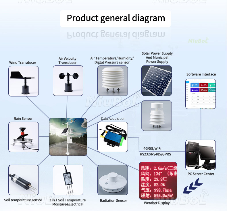
Analog versions provide separate moisture and temperature signals, so both require suitable receiving inputs. The RS485 version carries the two quantities digitally on one communication pair, with separate register identities.
No. Use its external supply and the specified signal wiring. Review the receiver's input circuit rather than assuming a two-wire transmitter arrangement or a self-powered sensor.
For the stated scales, it means 50% on the moisture channel or 25 degrees C on the temperature channel. Identify the signal before applying a conversion; the same current does not mean the same engineering number.
The matching two-register sequence starts with temperature at 0x0000 and moisture at 0x0001. Verify this order and the delivered configuration before assigning tags in the receiving software.
Treat it as invalid or missing for the affected channel before scaling. Do not convert it to a large engineering value or replace it with a genuine zero reading.
No. It checks the receiving input and conversion. The installed probe still needs separate checks of soil contact, temperature comparison and moisture response under a suitable field procedure.
Send the required output, receiver input specification or Modbus driver details, supply, cable distance and data destination. Identify both required measurements and any relevant negative-temperature conditions so the full acquisition path can be reviewed.
Reliable soil moisture and temperature sensor integration keeps electrical version, signal identity and conversion aligned. For the NBL-S-THR, verify the analog temperature offset or the two-word Modbus order, reject invalid measurements and confirm both records at the destination. These checks prevent a correctly installed soil probe from becoming an incorrectly scaled control input.
Next:Soil wetness sensor
Sensors & Weather Stations Catalog
 Agriculture Sensors and Weather Stations Catalog-NiuBoL.pdf
Weather Stations Catalog-NiuBoL.pdf
Agriculture Sensors Catalog-NiuBoL.pdf
Water Quality Sensor Catalog-NiuBoL.pdf
Related recommendations
 Multi-Depth Soil Sensor RS485
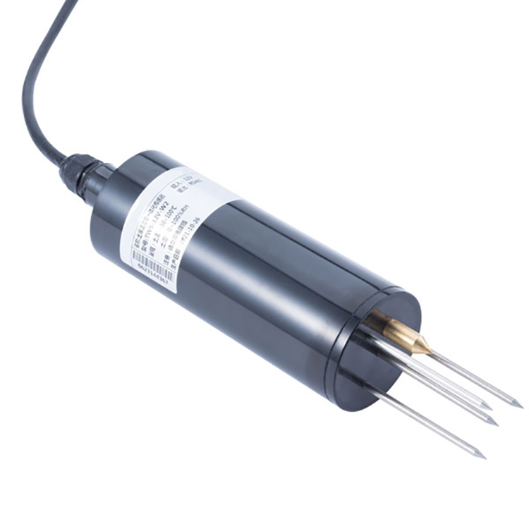 TDR Soil Moisture Sensor
 Pyranometer Solar Radiation Sensors
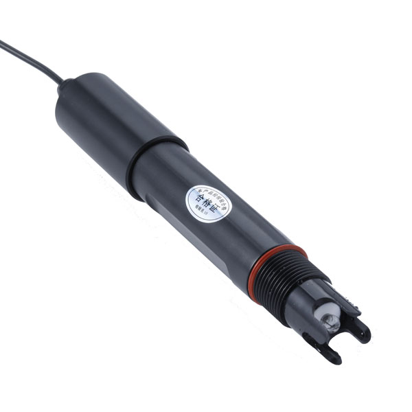 Soil ph sensor
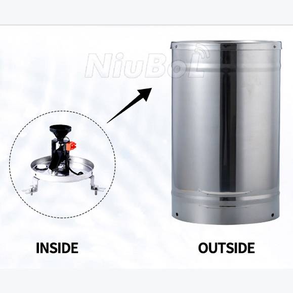 Tipping Bucket Rain Gauge
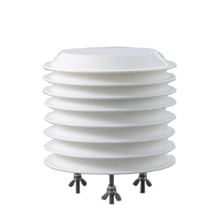 Air Temperature and Humidity Sensor


Screenshot, WhatsApp to identify the QR code
WhatsApp number:+8615367865107
(Click on WhatsApp to copy and add friends)

