





— Products —
 Consumer hotline +8618073152920
WhatsApp:+8615367865107
Address:Room 102, District D, Houhu Industrial Park, Yuelu District, Changsha City, Hunan Province, China
Level Sensors

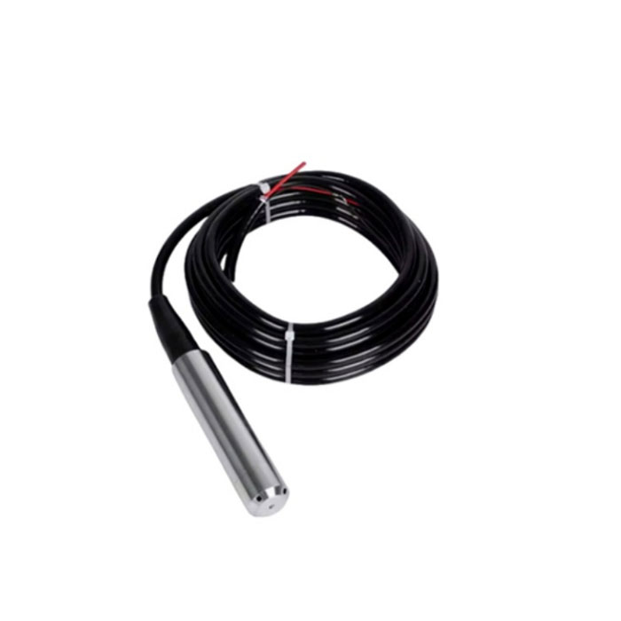
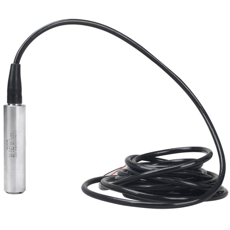
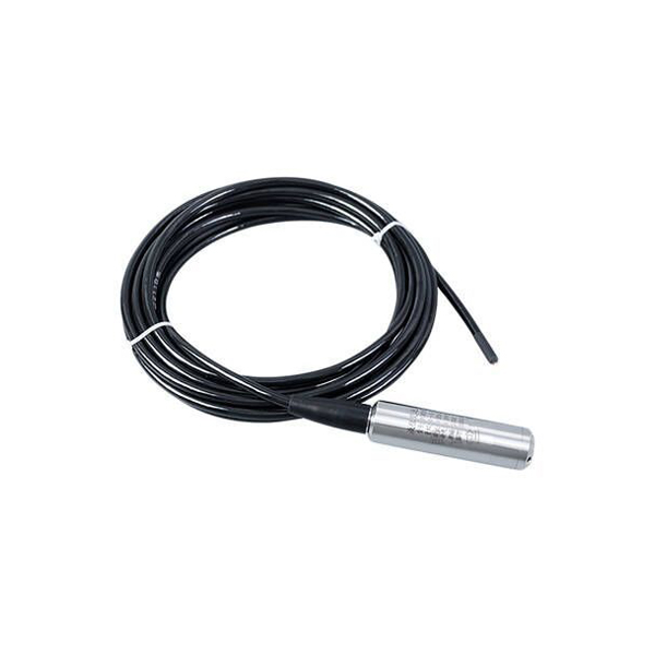
NiuBoL submersible level transmitter adopts imported diffused silicon core and ADI high-end chip, with RS485 communication and IP68 deep waterproof capability. The product has built-in automatic calibration algorithm, strong anti-interference ability, widely used in reservoir water level monitoring, sewage treatment, industrial oil tanks and smart agricultural irrigation systems, providing 2000m ultra-long distance signal transmission, the professional choice in the field of ···
Tel/WhatsApp:+8615367865107
Email:Arvin@niubol.com +Nearly 100 partner companies in more than 75 countries. We are committed to providing high-quality, practical products to meet your needs and help you solve problems. Our products comply with international standards and are certified with ISO, CE and RoHS.Product Details
The NiuBoL submersible level transmitter is designed for continuous liquid-level and water-depth measurement in wells, tanks, reservoirs, rivers and other applications where the sensing probe can be immersed directly in the liquid.
The transmitter uses the hydrostatic pressure measurement principle with a diffused-silicon piezoresistive sensing element. Pressure generated by the liquid column above the submerged probe is converted into level data and transmitted through RS485 Modbus RTU to a compatible PLC, RTU, data logger or IoT gateway.
With IP68 probe protection, a compact Φ26.8 mm stainless-steel body and configurable measurement ranges, this hydrostatic level transmitter is suitable for groundwater, reservoirs, storage tanks, water-treatment systems, irrigation projects and remote hydrological monitoring.
| Specification | Value |
| Product Type | Submersible Hydrostatic Level Transmitter |
| Measurement Principle | Hydrostatic pressure / diffused-silicon piezoresistive sensing |
| Measurement Range | 5 m standard configuration; 10–60 m ranges available depending on project requirements |
| Typical Accuracy | 0.2%FS / 0.5%FS depending on configuration |
| Long-Term Stability | ±0.2%FS/year |
| Power Supply | DC 10–30V, typical 24V DC |
| Static Power Consumption | ≤0.2W |
| Communication | RS485 |
| Protocol | Modbus RTU |
| Sampling Frequency | Up to 2400 samples/s |
| Protection Rating | IP68 |
| Probe Diameter | Φ26.8 mm |
| Housing Material | 304 / 316L stainless steel depending on configuration |
| Operating Temperature | -40 to 80°C |
| Recommended Medium Temperature | ≤60°C for long-term measurement |
| Overload Capacity | <1.5 × rated range |
| Typical Media | Water, oil and liquids compatible with the selected wetted materials |
A submersible level transmitter measures liquid depth from the hydrostatic pressure generated by the liquid column above the sensing diaphragm.
P = ρ × g × H
In this relationship, P is hydrostatic pressure, ρ is liquid density, g is gravitational acceleration and H is the liquid height above the probe.
When the probe is submerged, liquid pressure acts on the sensing diaphragm. The diffused-silicon sensing element converts the pressure into an electrical signal, and the internal electronics process the signal into digital level data for RS485 Modbus communication.
Submersible level monitoring systems can use a compact immersed probe connected directly to a data-acquisition system, or a split-type configuration where the submerged sensing probe is connected to a separate field display or transmitter housing.
The exact structure depends on the selected model and project requirements. A local display should not be assumed to be included with the standard RS485 probe unless it is specified in the quotation.
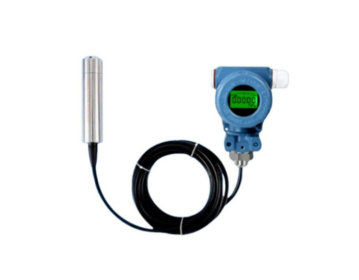
Example of a split-type level transmitter configuration with a submerged probe and separate field display.
The transmitter uses a vented cable so the reference side of the pressure sensor can remain connected to atmospheric pressure. This allows changes in barometric pressure to be compensated when calculating the hydrostatic pressure generated by the liquid column.
The vent path is therefore an important part of the measurement system. The cable should not be crushed or sharply bent, and the vent opening must remain dry and unobstructed.
The RS485 water level sensor can connect to compatible PLCs, RTUs, data loggers and IoT gateways for continuous water-level acquisition.
Submersible Level Transmitter → RS485 Modbus RTU → PLC / RTU / Data Logger → 4G / Ethernet / LoRaWAN Gateway → Cloud Platform or Private Server
The level transmitter itself provides the RS485 measurement data. Remote 4G, Ethernet, Wi-Fi, LoRaWAN, MQTT or HTTP communication requires a compatible data logger or IoT gateway.
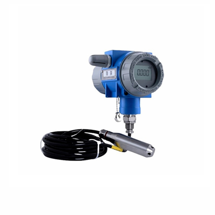
Split-type level transmitter example. Local display and housing configuration depend on the selected model.
RS485 Modbus and 4–20mA are both commonly used for liquid-level measurement. The correct output should be selected according to the receiving equipment and existing monitoring system.
| Selection Item | RS485 Modbus | 4–20mA |
| Signal Type | Digital | Analog current loop |
| Typical Receiver | PLC, RTU, data logger, IoT gateway | PLC analog input, process controller or display |
| Multi-Device Network | Supports Modbus multi-node system design | Normally one current loop per transmitter |
| Typical Selection | IoT, hydrology and digital monitoring systems | Existing industrial analog control systems |
If a dedicated 4–20mA transmitter is required, see theNBL-L-SMP4603 Submersible Level Transmitter with 4–20mA output.
The measurement range should be selected according to the maximum expected liquid depth rather than only the normal operating level. A suitable margin should be allowed for level fluctuations, while unnecessarily oversized ranges should be avoided.
| Project Information | Why It Matters |
| Maximum Liquid Depth | Determines the required pressure and level measurement range |
| Minimum / Maximum Operating Level | Helps determine suitable measurement margin |
| Liquid Density | Hydrostatic pressure depends on both liquid depth and density |
| Cable Length | Must reach from the submerged probe to the dry termination or control point |
| Tank / Well Geometry | Affects probe depth, fixing method and cable routing |
The standard transmitter uses 304 / 316L stainless-steel wetted components depending on configuration and is suitable for water, oil and other liquids that are compatible with the selected materials.
For wastewater, seawater, acids, alkalis, chemical liquids or other potentially corrosive media, provide the exact liquid composition, concentration and temperature before selecting the transmitter. Do not select a standard stainless-steel version only from the required level range.
| Medium | Selection Guidance |
| Clean Water | Standard hydrostatic level application |
| Groundwater | Suitable when probe range, cable length and installation depth are correctly selected |
| Oil | Confirm density, operating temperature and material compatibility |
| Wastewater | Confirm solids, chemical composition and corrosion conditions |
| Acid / Alkali / Chemical Liquid | Confirm chemical concentration, temperature and required wetted materials before ordering |
Install the probe at a position that represents the actual liquid level while protecting it from direct impact, heavy sediment accumulation and excessive cable movement.

Example level transmitter structure with submerged probe, vented cable and field display assembly.
| Installation Item | Recommendation |
| Probe Position | Install below the minimum liquid level and within the selected measurement range. |
| Sediment | Avoid placing the probe directly in accumulated silt. Where sediment is present, maintain suitable clearance above the sediment layer. |
| Strong Water Movement | Use suitable fixing, a protective pipe or another stabilization method where flow or waves may cause probe movement. |
| Vent Tube | Keep the vent path open, dry and protected from rainwater, dust and condensation. |
| Cable Routing | Avoid sharp bends, crushing and unnecessary mechanical tension on the vented cable. |
| Cable Length | Specify the required cable length when ordering whenever possible. |
| Sensor Diaphragm | Do not insert sharp objects into the pressure inlet or damage the sensing diaphragm. |
Thissubmersible water level sensoris suitable for applications where direct probe immersion is acceptable and continuous hydrostatic level measurement is required.
Groundwater Wells • Reservoirs & Lakes • Water Storage Tanks • Water Treatment
Irrigation Reservoirs • River Monitoring • Industrial Tanks • Hydrological Monitoring
Hydrostatic and radar sensors can both measure liquid level, but they use different measurement principles and installation methods.
| Selection Item | Submersible Hydrostatic Sensor | Radar Level Sensor |
| Measurement Principle | Hydrostatic pressure | Non-contact radar |
| Contact with Liquid | Yes | No |
| Installation Position | Probe immersed in liquid | Sensor mounted above liquid surface |
| Liquid Density | Density affects hydrostatic level conversion | Not based on hydrostatic density conversion |
| Typical Selection | Wells, tanks and submerged water-level monitoring | Non-contact tanks, reservoirs and applications where immersion is undesirable |
For correct model selection, the measured liquid and installation conditions are as important as the level range.
| Selection Item | Information to Provide |
| Measurement Range | Maximum liquid depth or required level range |
| Measured Medium | Water, wastewater, oil or exact chemical composition |
| Medium Temperature | Normal and maximum liquid temperature |
| Output | RS485 Modbus or 4–20mA according to the receiving equipment |
| Cable Length | Required length from submerged probe to dry termination or control cabinet |
| Accuracy | 0.2%FS or 0.5%FS requirement where applicable |
| Controller | PLC, RTU, data logger, display or IoT gateway |
| Installation Environment | Well, tank, river, reservoir, wastewater basin or other monitoring location |
A1. It is an immersion-type level sensor that measures hydrostatic pressure created by the liquid above the probe and converts that pressure into liquid-level data.
A2. The transmitter uses hydrostatic pressure measurement. Liquid level is calculated from the relationship between pressure, liquid density and liquid-column height.
A3. Yes. This configuration provides RS485 communication using Modbus RTU for compatible PLCs, RTUs, data loggers and IoT gateways.
A4. Yes. NiuBoL also provides dedicated 4–20mA submersible level transmitter models for industrial analog-input systems.
A5. The vent tube provides atmospheric-pressure compensation so changes in barometric pressure do not directly appear as changes in measured liquid level.
A6. It can be used when the liquid is compatible with the selected probe materials and the installation avoids excessive sediment or solids around the pressure inlet. Provide the wastewater composition when corrosion or chemical compatibility is uncertain.
A7. The standard stainless-steel version should not be selected for strong corrosive liquids without confirming compatibility. Provide the chemical, concentration and temperature so the required material or anti-corrosion configuration can be checked.
A8. It is preferable to specify the required cable length when ordering. Improper field modification can affect waterproof sealing or block the atmospheric vent path and cause measurement errors.
A9. Yes, by connecting the RS485 transmitter to a compatible 4G or LoRaWAN data logger or IoT gateway. These wireless functions are not built into the basic level transmitter.
A10. Provide the measurement range, liquid type, liquid temperature, required output, cable length, accuracy requirement, installation environment, quantity and the controller or gateway that will receive the level signal.
For model selection and quotation, provide the maximum liquid depth, measured medium, liquid temperature, required RS485 or 4–20mA output, cable length, accuracy requirement, quantity and installation environment.
For remote monitoring projects, also specify whether a data logger, 4G gateway, LoRaWAN communication, cloud platform or private-server integration is required.
Prev:no more
Next:Non-Contact Radar Flowmeter Sensor: All-Weather Flow Monitoring Solution for Smart Water Conservancy
Sensors & Weather Stations Catalog
 Agriculture Sensors and Weather Stations Catalog-NiuBoL.pdf
Weather Stations Catalog-NiuBoL.pdf
Agriculture Sensors Catalog-NiuBoL.pdf
Water Quality Sensor Catalog-NiuBoL.pdf
Related recommendations
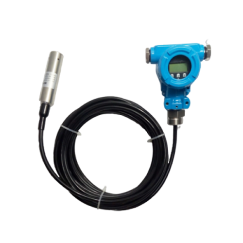 NBL-L-SMP4601 Split-Type Level Transmitter with Real-Time Level Display Output 4-20mA
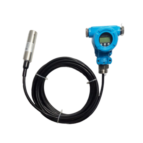 NBL-L-SMP4631 Series RS485/HART/Explosion-Proof Intelligent Split-Type Level Transmitter Sensor
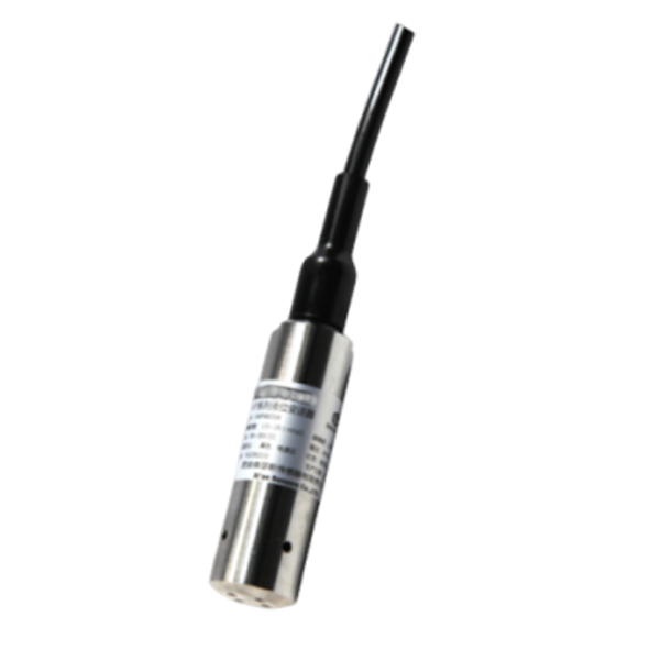 NBL-L-SMP4603 Submersible Level Transmitter Sensor 4-20mA
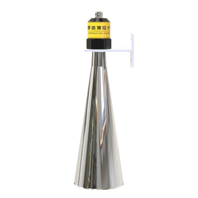 Non-Contact Radar Water Level Sensor RS485 Modbus FMCW | NiuBoL
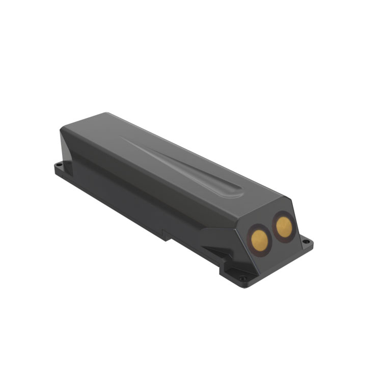 Doppler Velocity Meter for Open Channels, Rivers, and Non-Full Pipe Metering
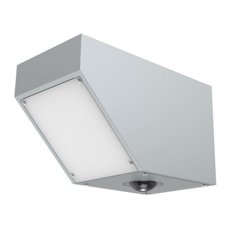 Non-Contact Radar Flowmeter Sensor: All-Weather Flow Monitoring Solution for Smart Water Conservancy


Screenshot, WhatsApp to identify the QR code
WhatsApp number:+8615367865107
(Click on WhatsApp to copy and add friends)

