





— Blogs —
—Products—
 Consumer hotline +8618073152920
WhatsApp:+8615367865107
Address:Room 102, District D, Houhu Industrial Park, Yuelu District, Changsha City, Hunan Province, China
Product knowledge
Time:2025-09-11 16:11:23 Popularity:1528
Automated weather station maintenance should preserve the measurement, not merely keep the equipment powered. Start with remote data checks, inspect the component associated with the symptom, and record readings before and after work. Clean, verify and calibrate as separate activities. Set service intervals from exposure, observed contamination and project requirements rather than applying one calibration schedule to every sensor.
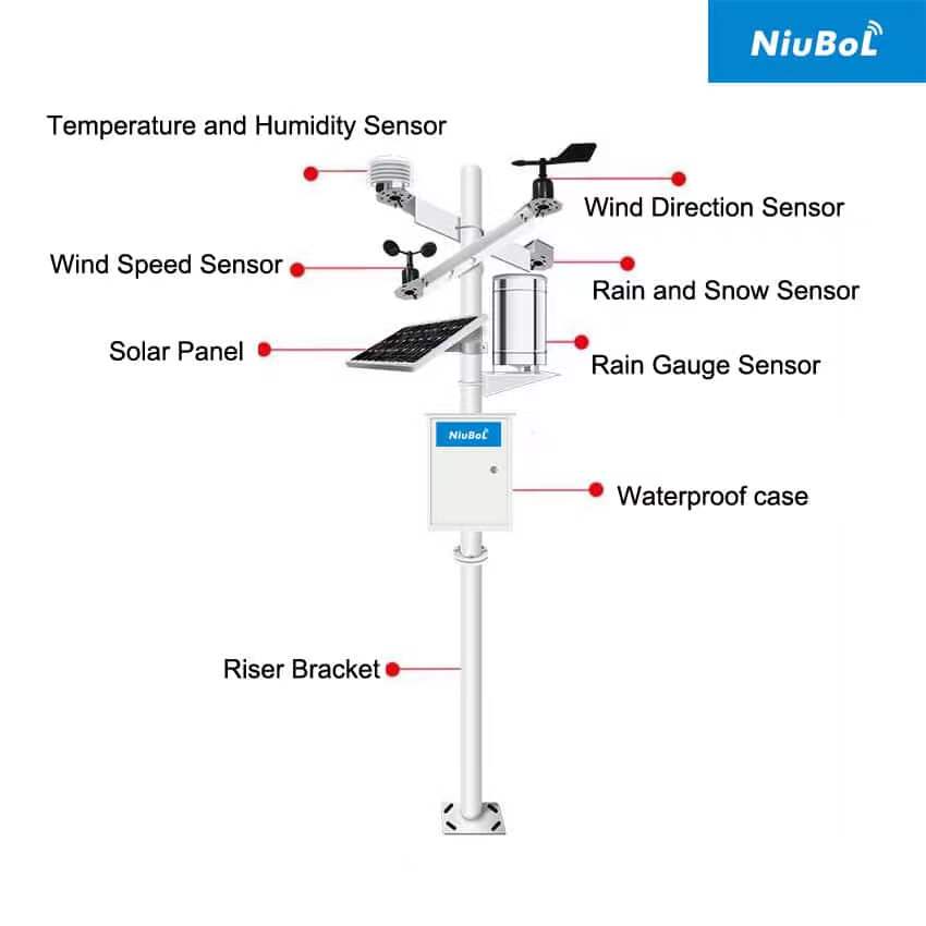
Before travelling, review which channels changed and when. If all channels disappear together, investigate station power, the logger and the uplink before ordering several replacement sensors. If only wind speed remains at zero while temperature and rainfall update normally, start with that sensor's mechanics, wiring and input configuration.
Compare recorded timestamps with arrival times. A communication outage followed by delayed uploads differs from a logger that stopped sampling. Keep the original time series available during diagnosis; replacing missing values with zero can make a data fault look like calm weather, no rain or freezing air.
Prepare a visit around the likely fault: correct cleaning materials, a verified reference instrument, approved spare parts and the configuration needed to test the affected input. Confirm safe access to the mast and cabinet. Work at height, electrical isolation and lightning exposure require the site's safety procedure, not an improvised sensor-maintenance checklist.
| Symptom | First checks | Verification after work |
|---|---|---|
| Wind speed remains zero | Free cup rotation, damage, cable and input type | Response at sensor/logger; distinguish true calm from a failed channel |
| Rainfall appears absent during rain | Funnel blockage, drainage, bucket movement and logger count | Controlled functional test with maintenance records separated from rainfall |
| Air temperature rises unusually in sun | Shield cleanliness, ventilation and changed surroundings | Comparison under matched exposure, not against a shaded indoor thermometer |
| Station resets near dawn or during upload | Battery condition, charging, connections and supply under load | Stable operation through the relevant low-charge or transmit period |
| Only remote data are missing | Local records, modem state, antenna and service | End-to-end delivery with original timestamps |
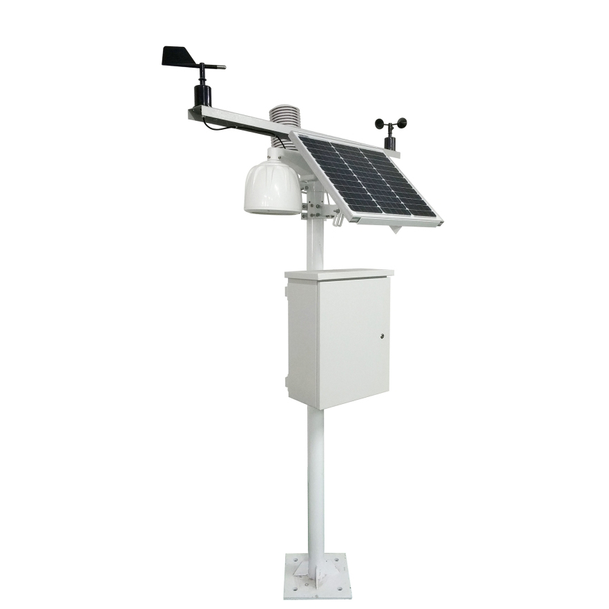
Inspect the collector, filter if fitted, funnel, bucket and drain. Remove contamination using a method compatible with the gauge surfaces. Avoid bending the mechanism or changing adjustment screws as part of routine cleaning. Check that the gauge is level and that water can leave without backing up into the measuring assembly.
For a tipping-bucket instrument, distinguish a functional count test from a calibration test. Manually moving a bucket can establish whether a contact and logger count operate; it does not verify rainfall accuracy. A controlled-volume test must use the specified delivery rate and procedure, because tipping behavior depends on flow.
The NiuBoL NBL-W-RS stainless steel rain gauge has a listed 0.2 mm resolution configuration. Do not apply that factor to every gauge at the site. Confirm the installed gauge's resolution and logger conversion, and identify test-generated tips so they do not become rainfall in the production record.
For a cup anemometer, inspect for deformation, obstruction and abnormal resistance to rotation. Do not force the rotor, apply an unapproved lubricant or use compressed air to spin it at an uncontrolled speed. A rotor that moves by hand has passed only a basic mechanical check; it has not established calibrated response across the measuring range.
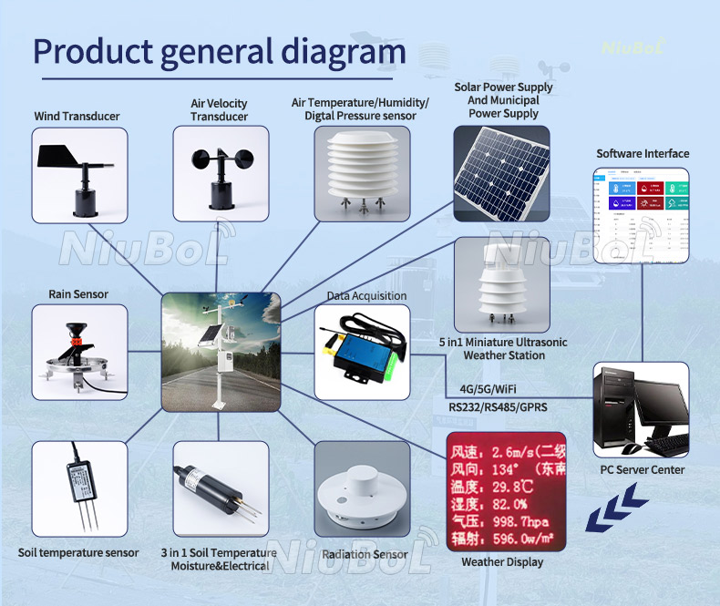
The NBL-W-SS wind speed sensor can be supplied with different outputs. A pulse-input fault needs a different test from a 4-20 mA or RS485 fault. Check the ordered version, supply and host conversion before replacing the sensing assembly. IP65 protection does not remove the need to protect cable joints or inspect outdoor connectors.
For wind direction, inspect vane movement and verify orientation against the installed model's reference marks. Do not turn the housing to make a short-term reading agree with a nearby vane in disturbed airflow. Record any change in alignment, height or mounting, because those changes affect interpretation of the observation series.
Inspect the radiation shield for deposits and blocked air paths. A sensor inside a clean-looking shield can still be affected by poor ventilation, nearby heat sources or changed ground cover. Check for new obstructions and exhaust outlets before assuming that an unusual temperature trend is sensor drift.
Use a reference comparison that measures the same air under comparable conditions. A brief reading from a handheld meter held in sunlight or near a warm cabinet is not a reliable calibration basis. Allow appropriate stabilization and record the comparison conditions and reference status.
Clean a solar radiation sensor's optical surface using its approved method, inspect leveling and check whether vegetation or new equipment creates shade. Do not paint, cover or polish a sensing surface as a generic protection measure. An ultrasonic wind head has no cup bearings, but its acoustic paths and mounting still require inspection.
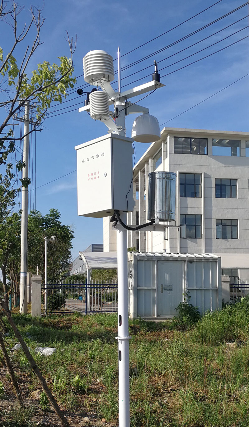
Inspect solar-panel shading, contamination and cable condition, then check charging behavior and battery performance under the actual load. An acceptable unloaded voltage does not establish useful battery capacity. A voltage drop during modem transmission can cause resets even when daytime readings appear normal.
Check cabinet seals, cable glands, drip loops, corrosion and signs of condensation. Tighten connections only to the approved method and torque; overtightening can damage glands, threads or seals. If water is present, find its entry route or condensation mechanism before returning equipment to service.
Record battery chemistry and controller settings before changing components. Do not substitute a different battery type solely because its nominal voltage matches. Check the charging profile, protection, temperature limits and required capacity against the station design.
| Component | Relevant specification | Service implication |
|---|---|---|
| NBL-W-SS cup anemometer | IP65; -40 to 80 degrees C; approximately 50 mW; output selected by version | Protect joints, keep rotor clear and use the correct electrical test |
| NBL-W-RS listed configuration | 0.2 mm resolution; 0-4 mm/min intensity range; operating temperature 0-50 degrees C | Use the correct tip factor and calibration flow; do not assume unheated snow measurement |
| Logger, modem and battery | Depends on the delivered station configuration | Check supply and charging requirements individually; no universal station power value |
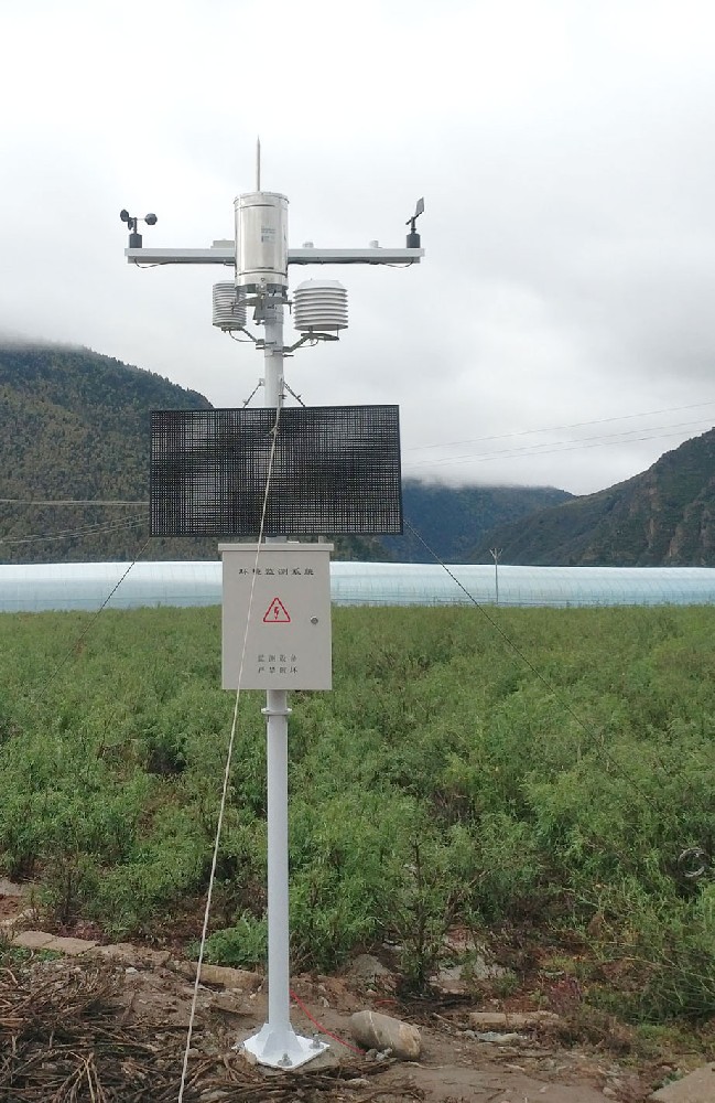
Before a firmware or configuration change, export the existing settings and available records. Confirm compatibility with connected sensors and the remote platform. An update can alter register handling, timestamps, channel units or upload behavior even when the device restarts successfully.
After work, test the affected channel at the logger and final destination. Verify clock and time zone, units, accumulation periods and any alarm setting touched during the visit. Compare the post-maintenance period with the pre-maintenance condition; document replaced parts and adjustments without silently rewriting the original observations.
The data logger and communications equipment should be checked as separate parts of the station. Local sampling can continue during an uplink outage only if the delivered configuration supports it. Test storage and retransmission rather than assuming every communications device is a recorder.
Use the first inspections to determine how quickly the rain collector blocks, optical surfaces become contaminated and cabinet connections deteriorate. Increase visits during the exposure that causes the problem, such as dust, heavy vegetation growth or storm damage. A clean site with stable checks can justify a different inspection pattern from a heavily contaminated installation.
Keep scheduled calibration and reference verification distinct from cleaning. Follow the applicable observation program and instrument procedure for required calibration. A universal six- or twelve-month adjustment rule can cause unnecessary intervention and still miss a blocked gauge that fails between visits.
For NiuBoL service support, provide the station and sensor models, affected channel, original configuration, recent readings and photographs of the installation. Include supply measurements under load where relevant. Those details help distinguish a replacement-part requirement from an installation, power or decoding fault.
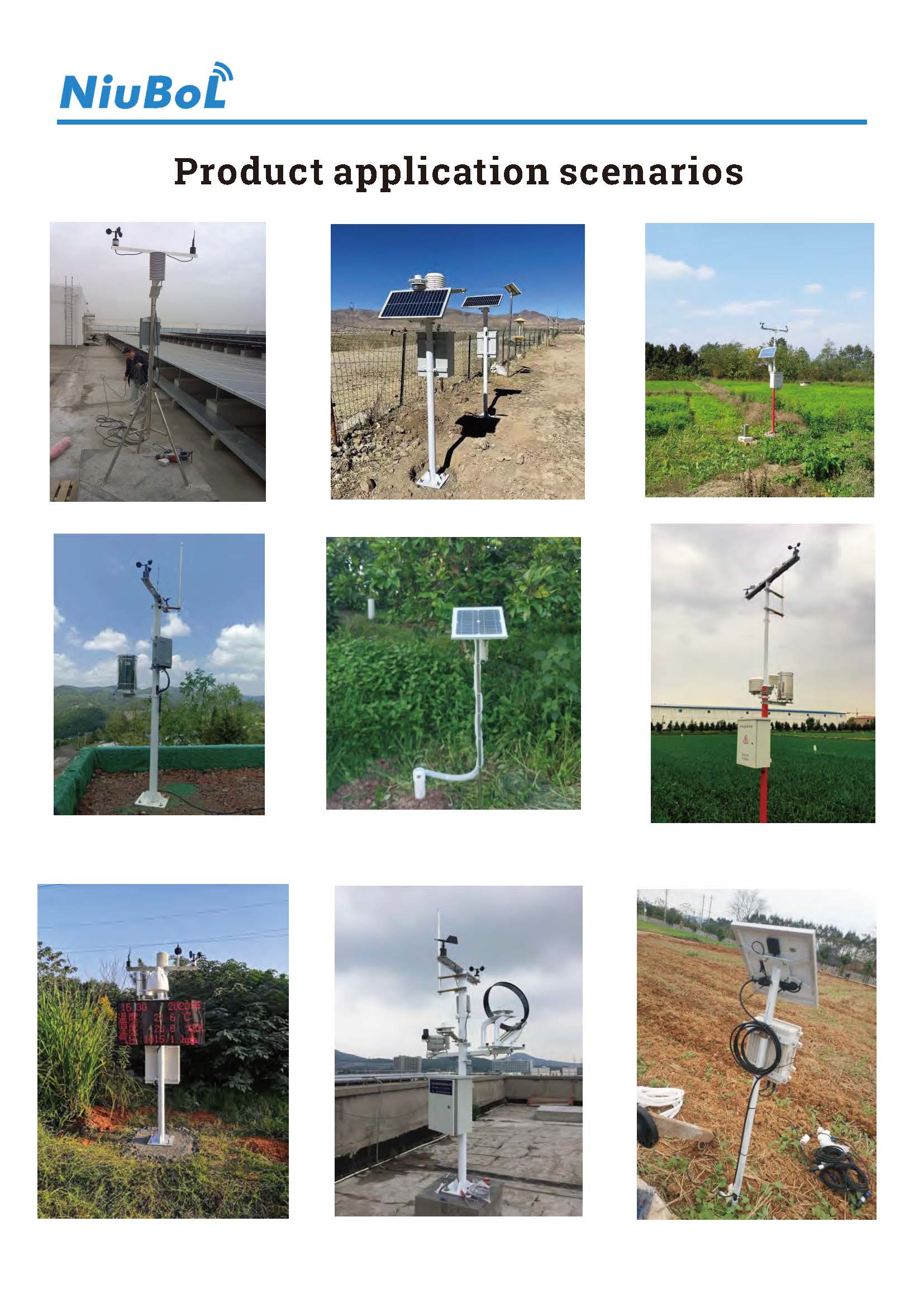
Use the instrument procedures and observation-program requirements as the starting point, then adjust inspection frequency to site fouling and faults. Cleaning may be needed more often than calibration. Recheck after severe weather or work that changes mounting or exposure.
No. First distinguish calm conditions from a stuck rotor, loss of power, wiring fault or stale data. Check other channels and timestamps, then test the installed output version. Do not declare a failure from one remote value alone.
That can provide a rough functional check, but uncontrolled volume and flow do not establish calibration. Use the required test apparatus and delivery procedure, and exclude or flag test counts in the rainfall record.
No. A glass optical surface, humidity element, rain collector and mechanical bearing have different requirements. Use component-specific methods and avoid unapproved solvents, coatings, scraping or lubrication.
Replace or repair a component that cannot meet the required verification after appropriate cleaning and diagnosis, or has damaged mechanics, seals or electronics. Calibration cannot correct a blocked collector, worn bearing or intermittent power connection.
Record the fault, pre-work readings, cleaning or replacement, configuration changes, reference checks and final host values. Identify test-generated rainfall and periods of interrupted observation. Include the next action if the fault is not fully resolved.
Effective automated weather station maintenance follows the symptom through sensing, power, logging and transmission. Preserve the pre-work record, correct the physical or electrical cause and verify the final measurement path. The useful outcome is a station whose observations can be interpreted, not simply one that has been cleaned and restarted.
Prev:Calibrating Soil Sensors for Long-Term Accuracy
Next:RS485, Modbus, LoRa and NB-IoT: How the Sensor Network Layers Fit
Related recommendations
Sensors & Weather Stations Catalog
 Agriculture Sensors and Weather Stations Catalog-NiuBoL.pdf
Weather Stations Catalog-NiuBoL.pdf
Agriculture Sensors Catalog-NiuBoL.pdf
Water Quality Sensor Catalog-NiuBoL.pdf
Related products
 Combined air temperature and relative humidity sensor
 TDR Soil Moisture & Temperature Sensor for irrigation| RS485 |4-20mA| NBL-S-THR
 Soil pH sensor RS485 soil Testing instrument soil ph meter for agriculture |NBL-S-PH
 Wind Speed sensor Output Modbus/RS485/Analog/0-5V/4-20mA
 Tipping bucket rain gauge for weather monitoring auto rainfall sensor RS485/Outdoor/stainless steel
 Pyranometer Solar Radiation Sensor 4-20mA/RS485


Screenshot, WhatsApp to identify the QR code
WhatsApp number:+8615367865107
(Click on WhatsApp to copy and add friends)

