





— Blogs —
—Products—
 Consumer hotline +8618073152920
WhatsApp:+8615367865107
Address:Room 102, District D, Houhu Industrial Park, Yuelu District, Changsha City, Hunan Province, China
Product knowledge
Time:2025-07-26 17:49:11 Popularity:1487
A soil water content sensor should be checked against the same water-content quantity that it reports. For volumetric water content, compare a matched soil reference in m3/m3 or %V/V, not a dry-mass percentage or air relative humidity. Check sampling position and probe contact before changing calibration; a difference between unlike measurements is not proof of sensor failure.
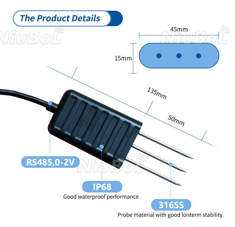
Volumetric water content is water volume divided by bulk soil volume. A value of 0.26 m3/m3 is 26%V/V. Gravimetric water content on a dry-mass basis is water mass divided by dry soil mass. Those percentages are not interchangeable, even when they come from the same soil sample.
Neither quantity is air relative humidity, so %RH is not an appropriate label for soil volumetric water content. Also distinguish water content from soil water potential: one describes the quantity of water, while the other describes its energy state. A sensor's 0-100% range does not imply that every value is physically attainable in a particular mineral soil, or that 100% means field capacity.
Before choosing a probe, agree the quantity the irrigation or research project needs. A project that records continuous water-content trends needs a different comparison from one that requires a soil-water-potential threshold. Additional EC or salinity channels provide context but do not convert either quantity into the other.

When a gravimetric reference is used, convert it with the dry soil bulk density and water density: volumetric fraction = dry-basis gravimetric fraction x dry bulk density / water density. Keep the units consistent. NC State Extension's soil-water calibration procedure explains why an undisturbed, known-volume sample is needed to determine bulk density.
For an illustrative calculation, a dry-basis water fraction of 0.20 and dry bulk density of 1.30 g/cm3 give 0.26 m3/m3 when water density is taken as 1.00 g/cm3. The comparable result is 26%V/V, not 20%V/V. These numbers demonstrate a conversion; they are not calibration results for a NiuBoL sensor or a particular soil.
Do not substitute particle density for bulk density. Bulk volume includes the pore space within the sample. A loose bag of excavated soil cannot by itself establish the original in-place bulk volume. Have a competent laboratory select the sampling and drying procedure appropriate to the soil or substrate.
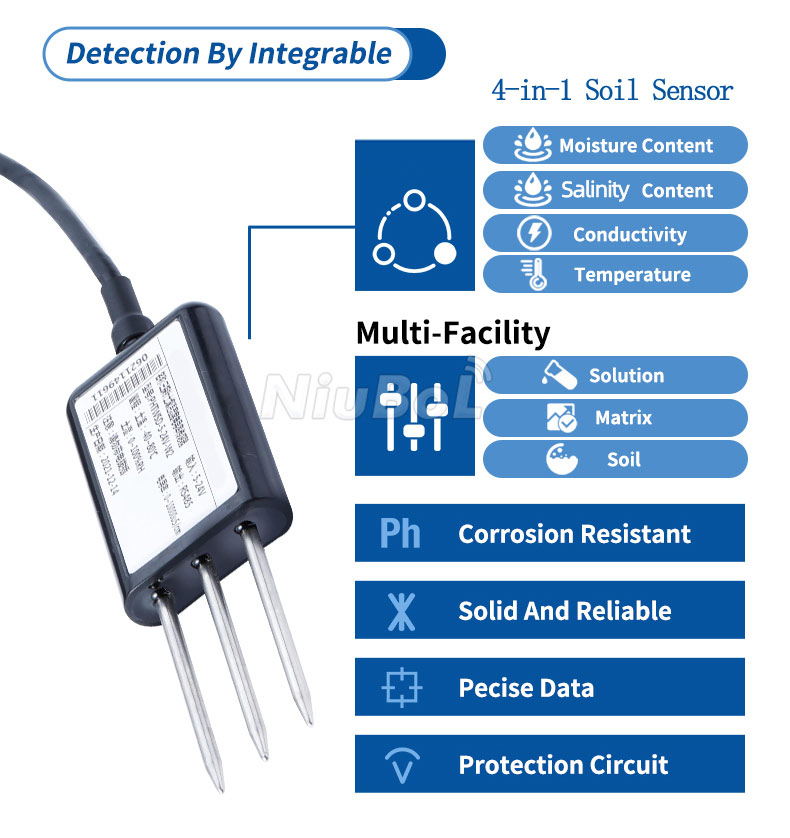
The probe and a destructive sample do not occupy exactly the same volume. Avoid presenting that unavoidable spatial difference as zero uncertainty. Sampling directly through the probe's measurement region also changes the installation, so plan the reference work before excavating around a permanent point.
| Selection item | NBL-S-TMC | NBL-S-THR |
|---|---|---|
| Channels | Temperature, moisture and EC | Temperature and moisture |
| Moisture principle | FDR | TDR |
| Moisture range / resolution | 0-100% / 0.1% | 0-100% / 0.1% |
| Specified moisture accuracy | +/-5% | +/-3% |
| Temperature measurement | -40 to 80 degree C; +/-0.5 degree C | -50 to 100 degree C; +/-0.5 degree C |
| Supply | 5-24 V DC or 12-24 V DC according to configuration | 12-24 V DC |
| Output | RS485 Modbus RTU | RS485 Modbus RTU, 4-20 mA or 0-5 V versions |
| Protection | IP68 probe | IP68 probe |
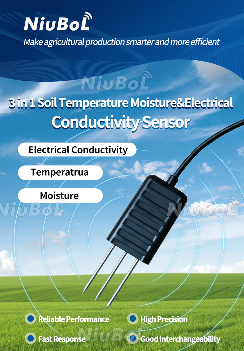
The NBL-S-TMC includes an EC channel where conductivity trends matter. The NBL-S-THR offers different receiving interfaces. Its operating environment is -40 to 80 degree C; the wider temperature measurement range does not authorize operation outside that environment.
For a separate salinity channel, the NBL-S-TMCS four-in-one probe is a different configuration, not an NBL-S-THR with additional labels. Select the actual channels required, and test their interpretation in the intended soil. Do not infer immunity to fertilizer, salts or soil texture from the FDR or TDR name.
A similar difference across matched conditions may justify investigating a systematic offset. A difference that grows with water content, changes after fertilizer application or appears only at one point requires a broader investigation. A single correction constant can hide those patterns instead of correcting them.
Check probe contact, local compaction, stones and air gaps. Review temperature and EC where available. University of Minnesota Extension notes that soil conditions and site-specific calibration matter for dielectric measurements. This is a reason to test the intended medium, not to reject every factory calibration automatically.

Do not wet a dry location merely to obtain a more reassuring sensor reading. That procedure no longer measures its original water condition. Deliberate wetting can be part of a documented response test, but record the applied event and distinguish it from an undisturbed field observation.
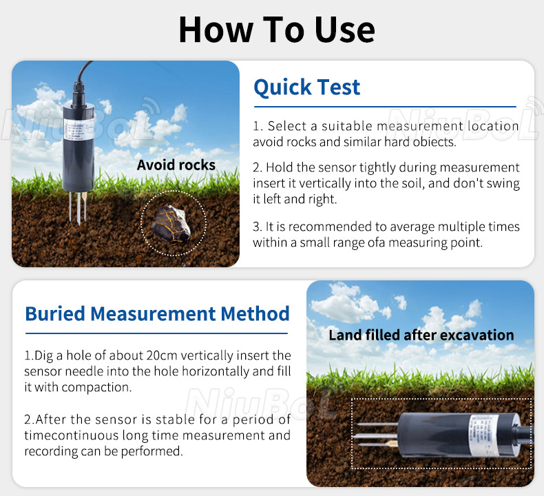
Likewise, removing and reinserting a probe for each comparison changes contact and local density. For a permanent installation, use the recommended insertion method for that probe, avoid rocking the electrodes to enlarge a hole, and document any excavation. An IP68 enclosure rating does not guarantee that the surrounding soil contact is correct.
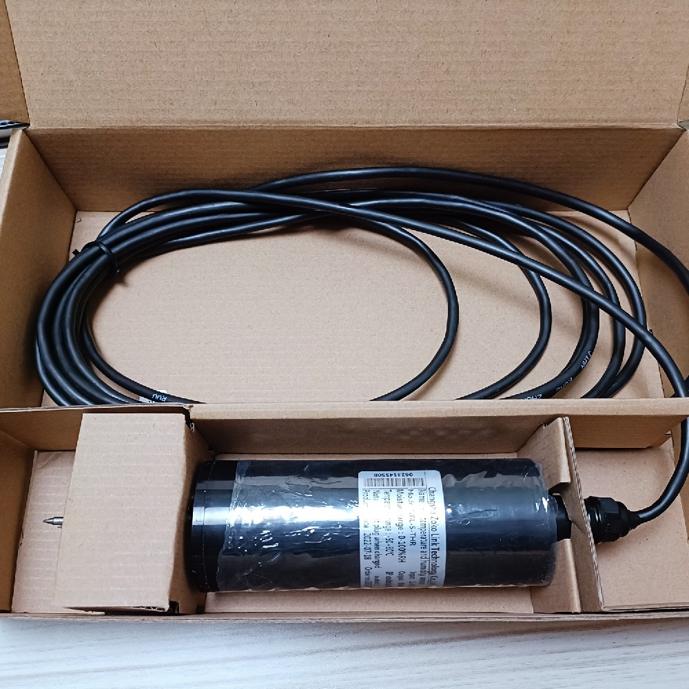
Before evaluating soil effects, confirm that the RS485 Modbus RTU register is decoded into the intended units and scale. For analog versions, check the configured electrical span against the receiving input. A value that is ten times too large should prompt a scaling check, not an immediate field-calibration adjustment.
Retain the raw value, decoded value, firmware or conversion revision and reference sample result. If a correction is applied in the logger or platform, keep the uncorrected series and state where the correction is performed. Do not silently apply it twice when the receiving application is changed.
For irrigation monitoring, acceptance may emphasize repeatable wetting and drying trends plus suitable reference agreement. A research project may require a documented error assessment over a defined range. Agree the method and limits before ordering rather than converting a catalog accuracy line into a universal field guarantee.
Send NiuBoL the soil or substrate description, required quantity, operating moisture conditions, receiving interface and proposed comparison method. Ask for configuration-specific details and a sample evaluation where necessary. Compare quotation scope without assuming that a more complex multi-parameter sensor automatically improves the moisture result.
No. For volumetric reporting, 25%V/V means 0.25 m3 of water per m3 of bulk soil. Relative humidity describes water vapour in air and is not the correct unit for that soil-water quantity.
Only if both results use the same basis. Convert a dry-mass fraction using measured dry bulk density and water density before comparing it with volumetric water content. Keep the sample location, time and method with the comparison.
No. One pair checks one condition and cannot establish performance across the operating range. Collect matched observations over relevant moisture conditions and investigate installation and sampling differences before fitting a correction.
No universal immunity should be assumed. Check the specified operating conditions, soil contact and reference agreement for the ordered sensor. Choose between NBL-S-THR and other configurations using actual channel and field requirements.
Preserve the model, output version, units, scaling and any approved correction procedure. Record replacements and recheck their response. A replacement that communicates correctly still needs a valid relationship with its soil measurement point.
 NBL-S-THR-Soil-temperature-and-moisture-sensors-Instruction-Manual-V4.0.pdf
NBL-S-TMC-Soil-temperature-and-moisture-conductivity-sensor.pdf
NBL-S-TM-Soil-temperature-and-moisture-sensor-Instruction-Manual-4.0.pdf
NBL-S-TMCS-Soil-Temperature-Humidity-Conductivity-and-Salinity-Sensor.pdf
Validate a soil water content sensor by matching the physical quantity, sampled soil and measurement time. Separate logger scaling, installation effects and soil-specific response. Keep the paired results and any correction procedure with the project record so later acceptance checks and repeat orders use the same basis.
Prev:Types of Precipitation Sensors: Match Depth, Intensity and Spatial Coverage
Next:Smart Soil Moisture Monitoring System: Diagnose Missed Irrigation
Related recommendations
Sensors & Weather Stations Catalog
Agriculture Sensors and Weather Stations Catalog-NiuBoL.pdf
Weather Stations Catalog-NiuBoL.pdf
Agriculture Sensors Catalog-NiuBoL.pdf
Water Quality Sensor Catalog-NiuBoL.pdf
Related products
 Combined air temperature and relative humidity sensor
 TDR Soil Moisture & Temperature Sensor for irrigation| RS485 |4-20mA| NBL-S-THR
 Soil pH sensor RS485 soil Testing instrument soil ph meter for agriculture |NBL-S-PH
 Wind Speed sensor Output Modbus/RS485/Analog/0-5V/4-20mA
 Tipping bucket rain gauge for weather monitoring auto rainfall sensor RS485/Outdoor/stainless steel
 Pyranometer Solar Radiation Sensor 4-20mA/RS485


Screenshot, WhatsApp to identify the QR code
WhatsApp number:+8615367865107
(Click on WhatsApp to copy and add friends)

