





— Download —
 Consumer hotline +8618073152920
WhatsApp:+8615367865107
Address:Room 102, District D, Houhu Industrial Park, Yuelu District, Changsha City, Hunan Province, China
All products

Wire the NiuBoL NBL-W-CO2 4-20mA sensor to a PLC using its 0-5000 ppm scale. Compare current tests, input loading and fault checks before specifying your installation.
Tel/WhatsApp:+8615367865107
Email:Arvin@niubol.com +Nearly 100 partner companies in more than 75 countries. We are committed to providing high-quality, practical products to meet your needs and help you solve problems. Our products comply with international standards and are certified with ISO, CE and RoHS.Product Details
Quick Answer: For the NBL-W-CO2 0-5000 ppm current-output version, concentration is C = (I - 4) / 16 x 5000, where I is measured in mA. The sensor uses 12-24 VDC and a receiving load of no more than 250 ohms. Confirm its separate power and signal connections from the delivered wiring diagram; a 4-20mA output does not mean the instrument can be wired as a generic two-wire loop-powered transmitter.
The NBL-W-CO2 is available with current or RS485 output. A PLC current input cannot read an RS485 pair, and changing software scaling cannot convert the interface. Check the instrument label, output option and concentration span before preparing terminals or ordering replacement devices.
| Item | Specification |
|---|---|
| Range | 0-5000 ppm |
| Accuracy | +/-(50 ppm + 3% of reading) |
| Resolution | 1 ppm |
| Supply | 12-24 VDC |
| Output | 4-20mA; RS485 is also listed as an option |
| Current-loop load | Up to 250 ohms |
| Cable | 2.5 m |
| Environment | -10 to 50 degrees C; 0-100% RH |
| Power | 0.2 W |
| Scaling | C = (I - 4) / 16 x 5000 ppm |
The NBL-W-CO2 V4.0 configuration uses a 0-5000 ppm span. A different span needs a different conversion. Resolution of 1 ppm describes the increment of the result, not an accuracy of 1 ppm.
Positive supply, supply return and current signal are separate electrical connections. The PLC or logger input must be compatible with that powered output arrangement. Identify the input module's passive or active behavior and common terminal before connecting it. Do not combine two powered outputs or assume that a diagram for a two-wire pressure transmitter applies to this sensor.
Complete wiring with power isolated. Check the delivered conductor schedule, terminal numbering and required signal return. Identify each conductor by its assigned electrical function and the supplied wiring diagram; do not rely on color alone. A replacement extension cable can use different colors without changing the electrical function of each conductor.
Measure supply voltage at the sensor while it is operating. The current-output load limit is 250 ohms. A 250 ohm receiver has a 5 V drop at 20 mA, calculated from V = I x R. Include added series loads and interface equipment in the design, but do not infer the permissible circuit from voltage subtraction alone; the transmitter and input module wiring requirements still apply.
Route the signal away from power-switching conductors where practical and follow the site's grounding method. For separate cabinets or different ground potentials, review whether an appropriate signal isolator is required. Cable extension and an isolator are engineering choices to check against supply, load and receiving-input specifications, not automatic accessories for every installation.
| Measured current | CO2 concentration for 0-5000 ppm |
|---|---|
| 4 mA | 0 ppm |
| 8 mA | 1250 ppm |
| 12 mA | 2500 ppm |
| 16 mA | 3750 ppm |
| 20 mA | 5000 ppm |
If the analog module already converts input current to engineering units, do not apply the same conversion again in the HMI. If it supplies raw ADC counts, use that module's documented count range and status information. There is no universal raw-count formula shared by every PLC.
A channel configured as 0-20mA will interpret the live-zero region incorrectly. A 12 mA input also cannot mean 2500 ppm when the ordered span is 0-2000 ppm; on that span it represents 1000 ppm. Keep the range on the sensor label consistent with the PLC scale, HMI tag and any gateway conversion.
For wider monitoring, the current input can belong to a PLC, RTU or compatible data logger. Remote communication is supplied by that acquisition system. The following station diagram illustrates the wider collection path; it does not mean a CO2 sensor alone includes every illustrated instrument or network option.
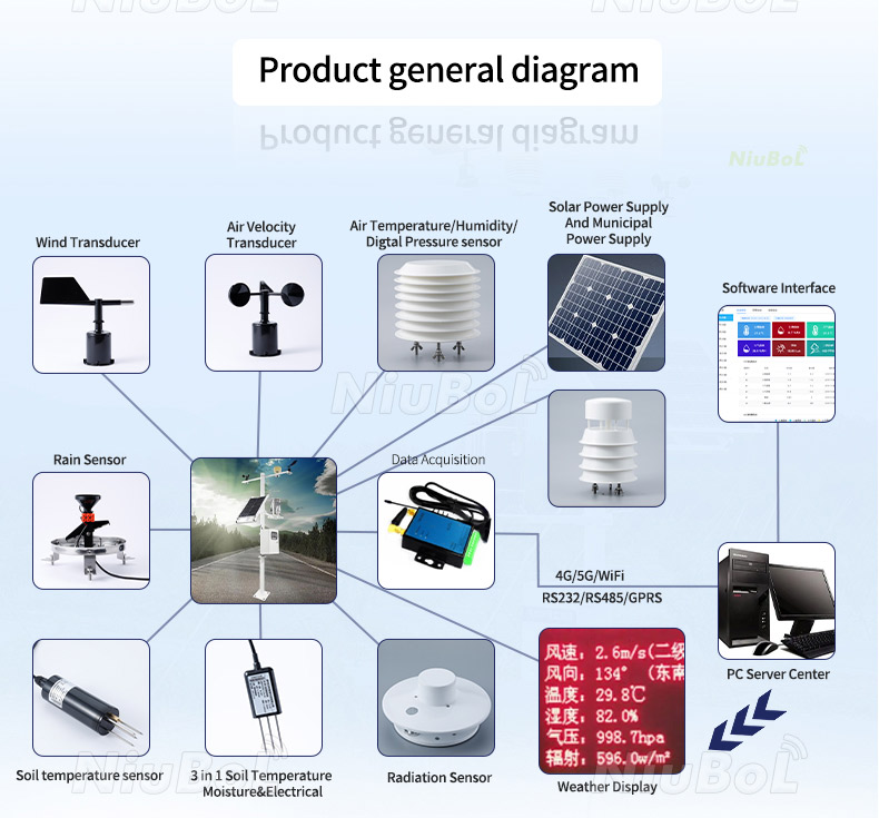
Use an appropriate current source at the receiving input to test the PLC scale, following the input module's procedure. Isolate the transmitter output as required and do not drive a test current into another active current output. Check 4, 12 and 20 mA at the PLC, then confirm the corresponding values at the HMI and stored record.
This test verifies the electrical receiving chain, not the CO2 sensing accuracy. Reconnect the sensor correctly and perform a separate comparison using a suitable reference or calibration method. Moving people close to the inlet can demonstrate a response, but exhaled air is not a traceable span gas and is not a calibration procedure.
The stated accuracy is +/-(50 ppm + 3% of reading). At 1000 ppm, that expression gives +/-80 ppm before considering a comparison instrument and test conditions. A tight control band should account for measurement uncertainty; adding display digits or averaging indefinitely does not remove a systematic offset.
| Symptom | Distinguishing check |
|---|---|
| PLC value wrong during current simulation | Check selected input mode, raw-count mapping and duplicate scaling. Inspect HMI conversion if the PLC value itself is correct. |
| Simulation correct; live reading differs from a reference | Check air location, comparison timing, sensor condition and reference suitability before changing the PLC span. |
| Value rises correctly but stops below the upper span | Investigate receiving load, supply at the device and interface limits. Do not assume low process concentration is the cause. |
| Zero or out-of-range current | Check power, wiring and input status. Use the delivered fault behavior; do not silently clamp every fault to valid zero CO2. |
Correct loop scaling cannot repair a poor location. Avoid direct breath, a dosing outlet, fresh-air diffuser, combustion exhaust or stagnant cabinet unless that local point is intentional. Large spaces may need multiple transmitters.
For occupied-space ventilation, place the instrument where it samples the air relevant to the ventilation zone, not inside a closed control cabinet. A sensor beside an open door or supply-air diffuser can respond to that local stream rather than the occupied space.
For greenhouse enrichment, avoid the immediate dosing plume unless that plume is the intended measurement. Review the reading during a supervised dosing or ventilation change. The controller needs a defined response to sensor failure; concentration trending alone is not a certified personnel-safety system or an independent dosing interlock.
For several analog points, each transmitter normally needs its own receiving channel and identifiable wiring path. Where the project instead needs many addressed sensors on a field bus, compare the RS485 integration arrangement before buying current-output versions. Modbus settings concern that alternative version, not the analog current signal.

Do not assume it is. This powered-output arrangement has separate supply, return and current-signal connections. Match that arrangement to the receiving input. Confirm the delivered diagram before wiring, especially when the PLC input supplies loop power.
A 4-20mA current through 250 ohms develops 1-5 V, not 0-5 V. That resistance reaches the listed load limit. Check the complete circuit and voltage-input requirements before using this arrangement, and do not add the resistor in series with another 250 ohm load.
It is outside the nominal measuring span, but the exact interpretation depends on transmitter behavior and input diagnostics. Check power and wiring and apply the specified fault policy. Use a standardized fault-current code only when the delivered instrument explicitly supports it.
No. Current simulation checks the receiving circuit and software conversion. Gas calibration or a suitable reference comparison checks the sensing response. Both are needed when the project acceptance requires confidence in the complete concentration channel.
Review total distance, supply at the sensor, receiving load, electrical noise and outdoor joints before agreeing an extension. Provide the required length with the PLC input details. Do not assume the standard 2.5 m cable specifies a universal maximum installed distance.
Provide concentration span, current-output requirement, supply, PLC or logger input, cable route and number of measurement zones. Describe whether the duty is ventilation monitoring or greenhouse enrichment, and state any reference-check, connector or interface requirements that affect the package.
Only if the air conditions and control objective justify that arrangement. Independently ventilated or dosed zones can need separate points. More precise electronics cannot correct a sensor installed in an air zone different from the one being controlled.
For this 4-20mA CO2 channel, confirm the output wiring and 0-5000 ppm span, test the receiving input with current simulation, then check the actual air measurement separately. NiuBoL can review the sensor configuration against your PLC input and installation requirements before quotation.
Sensors & Weather Stations Catalog
 Agriculture Sensors and Weather Stations Catalog-NiuBoL.pdf
Weather Stations Catalog-NiuBoL.pdf
Agriculture Sensors Catalog-NiuBoL.pdf
Water Quality Sensor Catalog-NiuBoL.pdf
Related recommendations
 Multi-Depth Soil Sensor RS485
 TDR Soil Moisture Sensor
 Pyranometer Solar Radiation Sensors
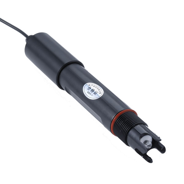 Soil ph sensor
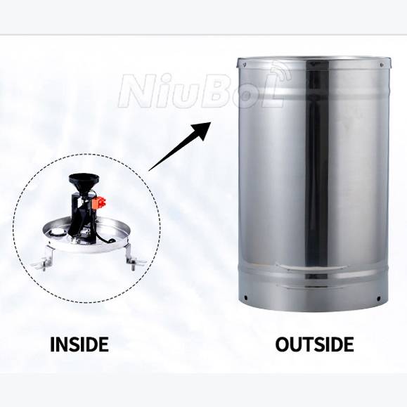 Tipping Bucket Rain Gauge
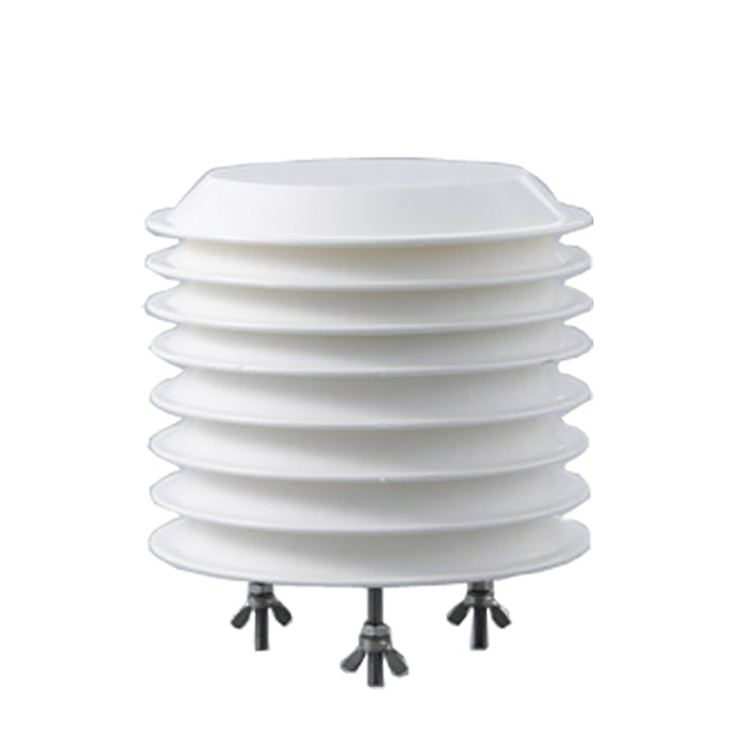 Air Temperature and Humidity Sensor


Screenshot, WhatsApp to identify the QR code
WhatsApp number:+8615367865107
(Click on WhatsApp to copy and add friends)

