

— Download —
 Consumer hotline +8618073152920
 WhatsApp:+8615367865107
Address:Room 102, District D, Houhu Industrial Park, Yuelu District, Changsha City, Hunan Province, China
All products
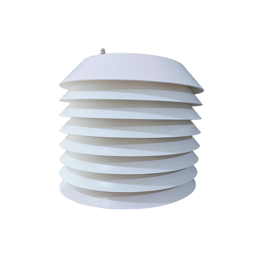
Integrate a NiuBoL Modbus RS485 CO2 sensor with a PLC or logger. Check register decoding, address setup and polling behavior before ordering the digital configuration.
Tel/WhatsApp:+8615367865107
Email:Arvin@niubol.com +Nearly 100 partner companies in more than 75 countries. We are committed to providing high-quality, practical products to meet your needs and help you solve problems. Our products comply with international standards and are certified with ISO, CE and RoHS.Product Details
Quick Answer: The NiuBoL Modbus RS485 CO2 sensor, model NBL-W-CO2, provides a 0-5000 ppm concentration channel with 12-24 VDC power. For the corresponding digital format, function 03 reads one 16-bit word at protocol address 0x0000; its integer value is already ppm. Commission one sensor at a time, verify address and byte interpretation, then connect the shared bus. The specified accuracy is +/-(50 ppm + 3% of reading), not a percentage of full scale.
The NBL-W-CO2 digital configuration returns one concentration word in the corresponding read format. It is not a two-word floating-point value and does not need the temperature-style division by ten used by some other environmental probes.
| Read item | Digital definition | Receiver check |
|---|---|---|
| Function | 03 | Read the supported holding-register format. |
| Protocol start address | 0x0000 | Check whether the software entry is zero-based or uses another display notation. |
| Word count | One 16-bit word | Do not decode as a two-register floating-point number. |
| Data byte order | High byte followed by low byte | Keep data byte order separate from CRC byte order. |
| Concentration conversion | Integer value in ppm | Do not apply another /10 or analog-span conversion. |
For example, data bytes 01 B4 form hexadecimal 0x01B4, or decimal 436, so the concentration is 436 ppm. Reversing the data bytes or treating them as ASCII produces a different result. This example explains decoding; it is not a field reference concentration or calibration target.
Some PLC software displays the first holding register using a notation different from the protocol's zero-based address. Check the request actually transmitted rather than assuming that typing a displayed register number always produces address 0x0000.
Validate the complete reply: requested device, function, byte count and CRC, followed by the value definition. A correctly shaped number from the wrong device address is not a valid observation for the intended greenhouse compartment or building zone.
| Parameter | Configuration |
|---|---|
| CO2 range | 0-5000 ppm |
| Accuracy | +/-(50 ppm + 3% of reading) |
| Resolution | 1 ppm |
| Supply and power | 12-24 VDC; 0.2 W |
| Digital output | RS485 Modbus RTU |
| Serial format | 9600 baud; eight data bits; no parity; match the delivered stop-bit setting |
| Communication interval | At least 1000 ms between communications |
| Standard cable and weight | 2.5 m; 140 g |
| Operating environment | -10 to 50 degrees C; 0-100% RH |
Do not assume additional baud rates or a universal device-count and cable-distance limit. The exact device options, receiver, topology, cable, protection and power distribution determine the network design. A data-sheet serial format is not permission to ignore those limits.
Digital output does not improve the gas-measurement accuracy. The ppm value still depends on representative air and the instrument's performance. The CO2 concentration sensor application guide addresses air-point selection and process interpretation separately from the network work here.
Bench-configure and label addresses before field installation. Keep an address schedule tied to physical location and platform tag. Duplicate addresses create intermittent or misleading data.
Configure and label a single device before it joins the shared network. Record its physical location, serial identity, communication address and application tag together. A label such as Greenhouse 2 is insufficient if the gateway stores the value under a different compartment.
Address setup can use device-specific commands rather than an ordinary measurement read. Use the supported configuration method for the delivered unit and isolate that unit during the change. Do not send an unreviewed setup command to a populated bus and assume only one device will act on it.
Choose unicast addresses that both the sensor and controller support, and keep broadcast behavior separate. After each change, read the configured address and concentration locally. Then add the unit to the trunk and confirm that previously installed devices still answer correctly.
Duplicate addresses can cause collisions, missing replies or confusing observations. A temporary successful reply does not prove that the bus is free of duplicates. Disconnecting and checking units individually is more informative than changing random baud and timeout settings on the whole network.
Daisy-chain devices along a main trunk and avoid uncontrolled star branches. Place termination at network ends where required and use biasing according to the master design.
RS485 A/B continuity does not prove adequate supply. Measure 12-24 VDC at the farthest sensor under load and include cable loss, gateway and other devices in the power budget.
Follow the delivered A/B and power labels. Do not assume that connector appearance or another vendor's terminal lettering defines this unit's pin assignment. Keep power conductors distinct from the differential communication pair and check the connection before energizing it.
Use the grounding, shielding, termination and biasing appropriate to the selected network. Do not add termination at every sensor or allow several unrelated devices to impose competing bias arrangements. The correct end-of-line treatment depends on the physical trunk and receiver design.
When devices fail only during modem transmission or another load change, measure the sensor supply under that condition. An idle cabinet reading can miss the voltage drop that interrupts a remote device. Repair the power or connection issue before treating repeated retries as the solution.
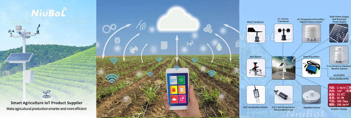
The environmental system diagram below shows acquisition and onward communication as separate stages. Optional wind and soil instruments in that diagram do not add measurement channels to this CO2 sensor.
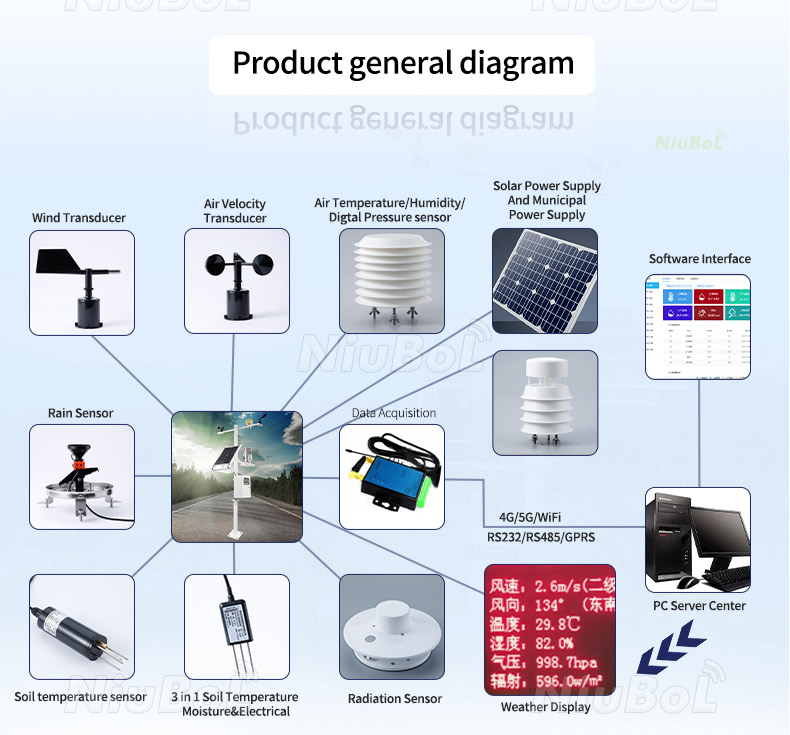
Respect the at-least-1000-ms communication interval for the selected configuration. Where it has not been established that faster interleaving is permitted, use a conservative request schedule. Multiple slaves on one physical bus share communication time; they do not all communicate simultaneously.
As a conservative planning example, eight devices with one request scheduled per second require about eight seconds for a complete sweep, before additional retry delays. This describes that assumed schedule, not a maximum network capacity or a required sensor count. Use an agreed, verified arrangement if the project needs a different refresh pattern.
Bound retries so one unavailable device cannot indefinitely delay every other observation. Store the time of the last successful acquisition for each point. A dashboard refreshed every second can still be displaying a value that has not been reacquired for several minutes.
A faster read does not establish a faster physical CO2 response. Keep the sensor's measurement dynamics, local polling, stored interval and upload period distinct. Confirm the actual gas-response requirement for the project rather than deriving it from the baud rate.
| Symptom | Next targeted check |
|---|---|
| No reply from a single isolated unit | Check loaded supply, wiring labels, serial format, address and supported read request. |
| Works alone but fails on the shared bus | Check duplicate addresses, trunk and branch layout, termination and network loading. |
| CRC-valid replies but implausible ppm | Check the selected register, word size, data byte order and unwanted conversion. |
| Local ppm is correct but remote ppm differs | Inspect gateway transformation, tag mapping, units and application conversion. |
| The displayed value survives a disconnected cable unchanged | Check last-success time and stale-data rules rather than accepting it as a new observation. |
Change one item at a time and keep a short record of the request, reply and result. Reconfiguring addresses, serial format and scaling together can hide the original fault. Start with one working local channel, then extend the same verified path to storage and remote export.
For a receiver test, use a known controlled value or suitable test tool without presenting it as a live gas measurement. For a sensor check, use an appropriate comparison in representative air. The two tests verify different parts of the channel.
Read each point locally and confirm its application tag, ppm and observation time remotely. Interrupt one sensor or bus segment through the agreed safe procedure and verify that only the affected observations become unavailable. Restore it and check automatic acquisition without an address or scale change.
Do not fill the interruption with a genuine zero or silently preserve an old valid status. For greenhouse enrichment or ventilation control, the controller needs an engineered response to unavailable input. A successful network recovery does not, by itself, qualify the application as a safety system.
For a Modbus RS485 CO2 sensor inquiry, provide the number and locations of points, receiver model, bus route, supply, desired refresh and remote destination. NiuBoL can then review the digital configuration, rather than assuming compatibility from the words RS485 and PLC alone.
One 16-bit integer in ppm from protocol address 0x0000 using function 03. Confirm the delivered configuration. Do not apply a two-register floating-point interpretation or an unrelated divide-by-ten conversion.
As data value 0x01B4, decimal 436, giving 436 ppm in this format. The data bytes are high first; their order should not be confused with the order of the CRC bytes.
Do not assume that a setup command uniquely targets one unconfigured device. Use the supported method with the intended unit isolated, label it and verify the result before adding it to the shared trunk.
The specified expression for this configuration is +/-(50 ppm + 3% of reading). The fixed term and reading-dependent term both matter; neither is replaced by the 1 ppm resolution.
No. Communication timing and gas response are different properties. Respect the allowed read interval, and confirm the measurement response required for the actual process.
The application can redraw a cached value without a new sensor acquisition. Retain and check the last successful observation time and quality status for each point, not only the screen refresh time.
Keep device identity, location, address, serial format, read definition and a verified ppm observation at local and remote stages. Add the interruption and recovery result so later maintenance can distinguish a wiring fault from a changed map.
Integrate the Modbus RS485 CO2 sensor through a verified single-word decode, unique device identity and a realistic polling schedule. Check power, bus communication and data interpretation separately, then test interruption recovery. Send NiuBoL the receiver and network layout for digital configuration review.
Sensors & Weather Stations Catalog
 Agriculture Sensors and Weather Stations Catalog-NiuBoL.pdf
Weather Stations Catalog-NiuBoL.pdf
Agriculture Sensors Catalog-NiuBoL.pdf
Water Quality Sensor Catalog-NiuBoL.pdf
Related recommendations
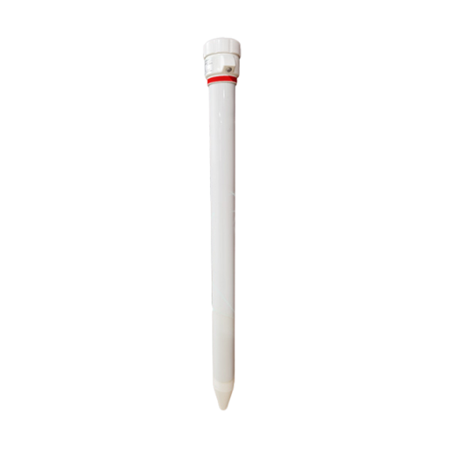 Multi-Depth Soil Sensor RS485
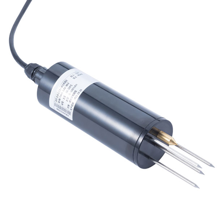 TDR Soil Moisture Sensor
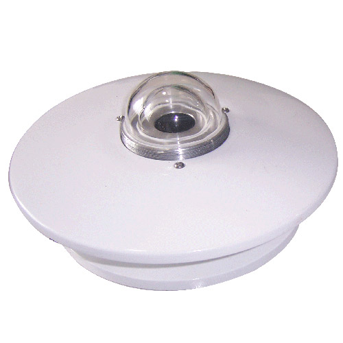 Pyranometer Solar Radiation Sensors
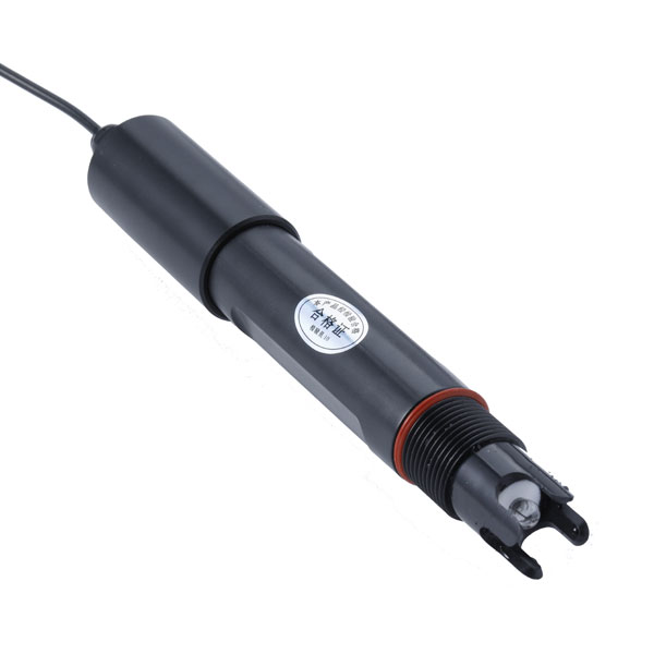 Soil ph sensor
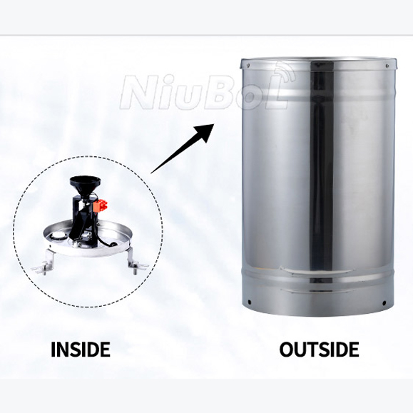 Tipping Bucket Rain Gauge
 Air Temperature and Humidity Sensor

Screenshot, WhatsApp to identify the QR code
WhatsApp number:+8615367865107
(Click on WhatsApp to copy and add friends)