





— Products —
 Consumer hotline +8618073152920
WhatsApp:+8615367865107
Address:Room 102, District D, Houhu Industrial Park, Yuelu District, Changsha City, Hunan Province, China
Weather Stations


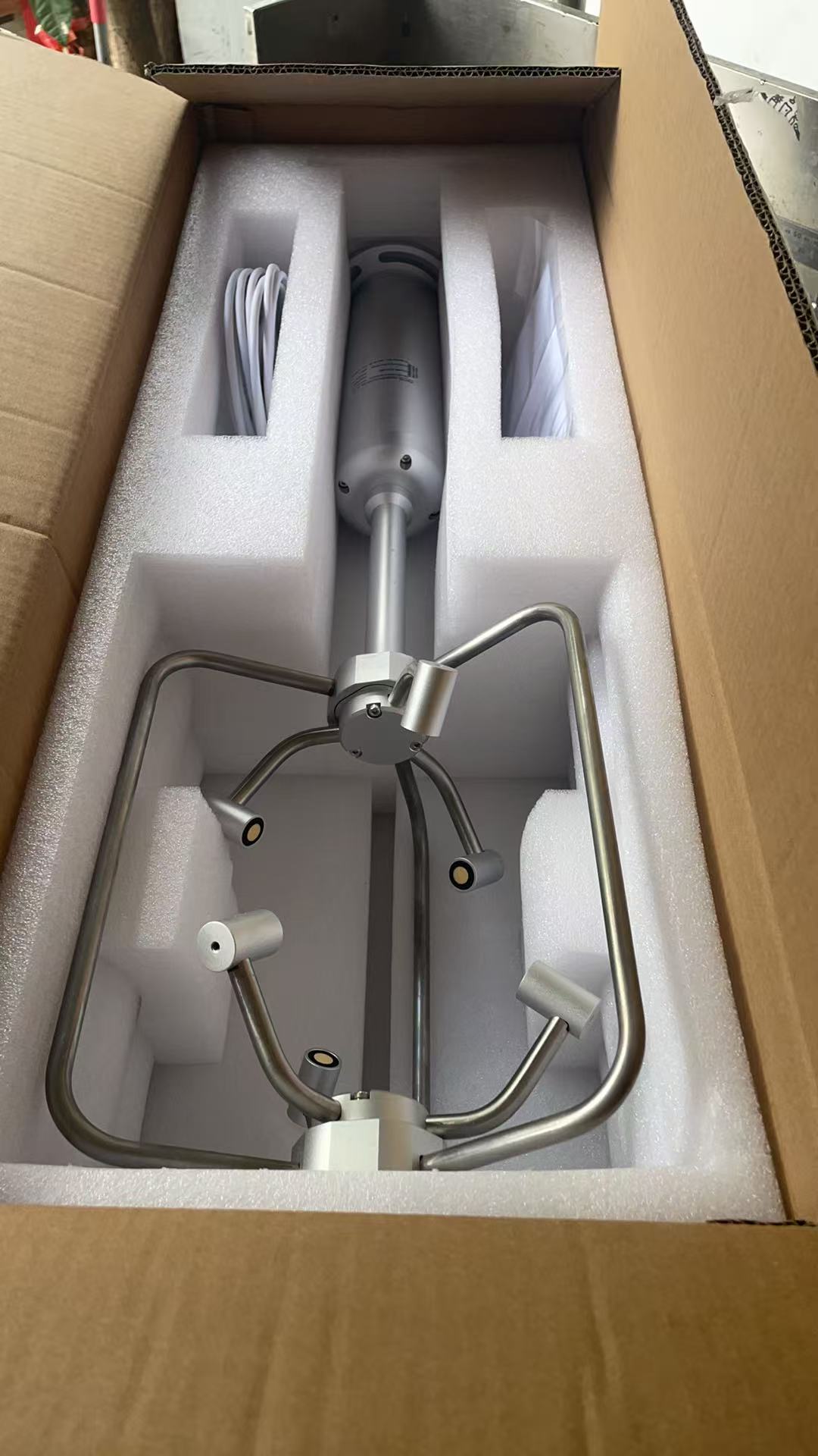
NBL-W-3D-UWDS 3D Ultrasonic Anemometer adopts advanced ultrasonic measurement technology and unique structural design, which greatly reduces the influence of wind resistance and improves the accuracy of measurement. All-metal material, without any moving parts, sturdy and durable, can simultaneously measure the horizontal and vertical wind direction, X/Y/Z-axis wind speed (i.e. U, V, W vector output). Widely used in urban environment monitoring, wind power generation, meteoro···
Tel/WhatsApp:+8615367865107
Email:Arvin@niubol.com +Nearly 100 partner companies in more than 75 countries. We are committed to providing high-quality, practical products to meet your needs and help you solve problems. Our products comply with international standards and are certified with ISO, CE and RoHS.Product Details
The NBL-W-3D-UWDS 3D ultrasonic anemometer measures three-dimensional wind vectors using three pairs of ultrasonic transducers. It provides resultant wind speed, horizontal wind direction, vertical wind direction and X/Y/Z-axis wind speed components, commonly represented as U, V and W.
Unlike a conventional cup anemometer and wind vane, the sensor has no rotating wind-measurement components. Ultrasonic transit-time measurement allows both horizontal and vertical airflow to be captured, making the instrument suitable for applications where a conventional 2D wind sensor does not provide enough information.
With a wind speed range up to 60 m/s, RS485 Modbus communication, DC 9–24V supply and IP66 protection, the sensor can be integrated with compatible data loggers, PLCs, research acquisition systems and IoT gateways for meteorological, wind-energy, bridge, tunnel, marine and airflow-monitoring projects.
| Specification | Value |
| Model | NBL-W-3D-UWDS |
| Product Type | 3D Ultrasonic / Sonic Anemometer |
| Measurement Principle | Ultrasonic Transit-Time / Time-of-Flight Measurement |
| Measured Outputs | Resultant Wind Speed, Horizontal Wind Direction, Vertical Wind Direction and X/Y/Z Wind Speed Components |
| Power Supply | DC 9–24V |
| Signal Output | RS485 |
| Communication Protocol | Modbus RTU |
| Baud Rate | 9600 bps |
| Average Power Consumption | 2 W |
| Operating Temperature | -40 to 80°C |
| Operating Humidity | 0–100% RH |
| Protection Rating | IP66 |
| Housing | All-Metal Structure |
| Moving Wind-Measurement Parts | None |
| Measurement | Range | Accuracy | Resolution |
| Resultant Wind Speed | 0–60 m/s | ±(0.5 + 3% FS) | 0.01 m/s |
| Horizontal Wind Direction | 0–359° | ±3° | 1° |
| Vertical Wind Direction | -90 to +90° | ±3° | 1° |
| X-Axis Wind Speed | -60 to +60 m/s | ±(0.5 + 3% FS) | 0.01 m/s |
| Y-Axis Wind Speed | -60 to +60 m/s | ±(0.5 + 3% FS) | 0.01 m/s |
| Z-Axis Wind Speed | -60 to +60 m/s | ±(0.5 + 3% FS) | 0.01 m/s |
A standard 2D anemometer describes airflow mainly in the horizontal plane. A 3D ultrasonic anemometer additionally measures the vertical airflow component.
| Component | Meaning | Why It Matters |
| U / X | Wind component along one horizontal axis | Used with the other vector components to describe airflow direction and magnitude |
| V / Y | Wind component along the second horizontal axis | Provides the second horizontal component required for vector wind analysis |
| W / Z | Vertical airflow component | Useful for vertical airflow, turbulence and atmospheric-flow studies |
The instrument also calculates resultant wind speed and derives horizontal and vertical wind direction from the three measured vector components.
The NBL-W-3D-UWDS uses three pairs of ultrasonic transducers arranged in three-dimensional space. Each pair alternately transmits and receives ultrasonic signals.
Air movement changes the travel time of sound between opposing transducers. A signal travelling with the airflow reaches the opposite transducer differently from a signal travelling against the airflow. By measuring these transit-time differences, the instrument calculates wind velocity along the X, Y and Z axes.
The three vector components are then used to calculate resultant wind speed, horizontal wind direction and vertical wind direction. This allows the sensor to describe airflow in three dimensions rather than only in the horizontal plane.
| Feature | Project Value |
| Three-Axis Wind Measurement | Measures horizontal and vertical airflow instead of only 2D wind direction |
| U / V / W Vector Output | Provides X/Y/Z wind-speed components for airflow and research analysis |
| No Conventional Moving Wind Parts | Eliminates rotating cups and a mechanical wind vane |
| 0.01 m/s Resolution | Fine digital wind-speed resolution |
| RS485 Modbus | Integration with compatible research loggers, PLCs and IoT systems |
| All-Metal Structure | Designed for fixed outdoor and industrial wind-monitoring installations |
| IP66 | Outdoor environmental monitoring |
Three pairs of ultrasonic transducers are positioned around the measurement volume so wind components can be measured along three axes. The sensor has an approximate overall height of 755 mm and an outer measurement-frame diameter of approximately 280 mm.

The 3D ultrasonic anemometer with RS485 Modbus provides six main real-time wind values through one digital communication interface.
| Communication Item | Specification |
| Interface | RS485 |
| Protocol | Modbus RTU |
| Baud Rate | 9600 bps |
| Device Address | 0–255 |
| Real-Time Read Function | 03 |
| Measurement Registers | 6 |
| Data Position | Measurement |
| 1 | Resultant Wind Speed |
| 2 | Horizontal Wind Direction |
| 3 | Vertical Wind Direction |
| 4 | X-Axis Wind Speed |
| 5 | Y-Axis Wind Speed |
| 6 | Z-Axis Wind Speed |
For device address 01, the manual provides the following command to read the six real-time measurement registers:
01 03 00 00 00 06 C5 C8
The returned data follows the measurement order shown above. Wind-speed components use 0.01 m/s resolution, while direction channels use 1° resolution.
| Wire Color | Function |
| Red | Power Input Positive |
| Black | Power Input Negative |
| Yellow | RS485 A+ |
| Blue | RS485 B− |
The wiring label supplied with the actual communication cable should be used as the final wiring reference. Complete and verify all connections before applying power.
The NBL-W-3D-UWDS uses an all-metal housing and transducer support structure. The fixed ultrasonic transducers do not require conventional wind cups or a mechanical vane to rotate with the airflow.

Install the 3D ultrasonic anemometer in an open location where surrounding structures do not significantly obstruct or distort the airflow. The sensor should normally be mounted at the top of the supporting mast or structure where practical.
| Installation Item | Recommendation |
| Mounting Position | Install at the top of the mast or support structure where practical. |
| Minimum Height | The product manual recommends at least 2 m above the ground for general installation. |
| Airflow | Keep the measurement volume clear of nearby buildings, trees, poles and other airflow obstructions. |
| Direction Alignment | The top reference mark corresponds to the 0° phase. Determine the required reference direction before fixing the sensor; north is commonly used. |
| Mounting Hardware | Secure the sensor to the bracket using the four mounting bolts and nuts. |
| Cable | Lock the aviation connector correctly and provide appropriate strain relief. |
| Radio / Radar Sources | Avoid installation directly beside radar or strong radio transmitters. |
| Power Supply | Provide continuous DC 9–24V. |
| Measurement | 2D Ultrasonic Anemometer | 3D Ultrasonic Anemometer |
| Horizontal Wind Speed | Yes | Yes |
| Horizontal Wind Direction | Yes | Yes |
| Vertical Wind Component | No | Yes |
| Vertical Wind Direction | No | Yes |
| U / V / W Output | Normally U / V only | U / V / W |
| Typical Use | Routine weather and horizontal wind monitoring | 3D airflow, research, structural wind and vertical-flow monitoring |
| Selection Item | Mechanical Cup / Vane | NBL-W-3D-UWDS |
| Wind Measurement | Mechanical rotation | Ultrasonic transit time |
| Moving Parts | Yes | No conventional moving wind parts |
| Vertical Wind | Normally not measured | Measured |
| Vector Components | Not typically available | X / Y / Z |
| Typical Selection | General weather stations and basic wind monitoring | Three-dimensional airflow and specialized monitoring |
The NBL-W-3D-UWDS is most useful in projects where vertical airflow or three-axis wind components provide information that cannot be obtained from a conventional 2D wind sensor.
Meteorological Research • Wind Energy • Bridge Wind Monitoring • Tunnel Airflow
Airports & Aviation • Marine & Ports • Urban Wind Studies • Environmental Research
Eddy covariance systems normally require more than simply having U/V/W wind outputs. Projects may specify high-frequency sampling, sonic temperature, synchronization with gas analyzers, timestamp accuracy, raw-data access and particular data-output formats.
The NBL-W-3D-UWDS should therefore not automatically be presented as an eddy-covariance-grade sonic anemometer unless the project's required sampling frequency, data protocol and research specifications have been reviewed and confirmed.
3D Ultrasonic Anemometer → RS485 Modbus → Data Logger / PLC / Research Acquisition System → Ethernet / 4G → Cloud Platform or Private Server
The anemometer itself provides the RS485 wind measurements. Remote Ethernet, 4G, Wi-Fi, MQTT or server communication requires a compatible data logger or gateway.
| Selection Item | Information to Confirm |
| Required Wind Data | Resultant wind speed, horizontal / vertical direction and whether U / V / W components are required |
| Wind Speed Range | Confirm whether the ±60 m/s component range meets the project requirement |
| Communication | RS485 Modbus and receiving data logger / PLC compatibility |
| Sampling Requirement | Especially important for turbulence or research applications |
| Raw Data Requirement | Confirm whether processed Modbus values are sufficient or research-grade raw data is required |
| Mounting Environment | Mast, bridge, tunnel, marine platform, airport or research tower |
| Cable Length | Distance from sensor to logger or control cabinet |
| Power Supply | Available DC supply and total monitoring-system power budget |
A1. It measures resultant wind speed, horizontal wind direction, vertical wind direction and X/Y/Z-axis wind speed components.
A2. Resultant wind speed is 0–60 m/s. X, Y and Z wind components are specified from -60 to +60 m/s.
A3. A 2D wind sensor measures airflow mainly in the horizontal plane. A 3D anemometer additionally measures the vertical wind component and provides three-axis U/V/W wind data.
A4. It has no conventional rotating wind cups or mechanical wind vane. Wind is measured using ultrasonic transit time between fixed transducers.
A5. Yes. The sensor provides RS485 Modbus communication and returns six main real-time wind parameters.
A6. U and V represent wind components along two horizontal axes, while W represents the vertical airflow component.
A7. Yes. The specified vertical wind direction range is -90° to +90° with 1° resolution.
A8. Yes. Bridge, tunnel and structural airflow monitoring are typical applications where multi-axis wind information can be useful.
A9. Do not select it for eddy covariance only because it provides U/V/W data. Eddy-covariance projects may require specific sampling rates, sonic temperature, synchronization and raw-data functions that must be checked separately.
A10. Provide the quantity, application, required wind parameters, sampling requirements, cable length, mounting environment, power supply and receiving data logger, PLC or research acquisition system.
 NBL-W-3D-UWDS-3D-Ultrasonic-Anemometer-Datasheet.pdf
For quotation and model confirmation, provide the application, required wind parameters, quantity, cable length, installation height, mounting environment, power supply and receiving RS485 data-acquisition equipment.
For wind-energy, turbulence, structural engineering or research projects, also provide the required sampling rate, data-output format, raw-data requirements, synchronization requirements and whether additional measurements such as sonic temperature are required. This allows suitability to be confirmed before ordering.
Sensors & Weather Stations Catalog
Agriculture Sensors and Weather Stations Catalog-NiuBoL.pdf
Weather Stations Catalog-NiuBoL.pdf
Agriculture Sensors Catalog-NiuBoL.pdf
Water Quality Sensor Catalog-NiuBoL.pdf
Related recommendations
 Wind Speed sensor Output Modbus/RS485/Analog/0-5V/4-20mA
 Tipping bucket rain gauge for weather monitoring auto rainfall sensor RS485/Outdoor/stainless steel
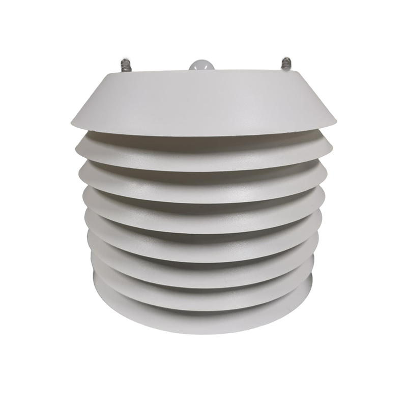 5-in-1 Temperature, Humidity, Air Pressure, Illumination, CO2 Sensor
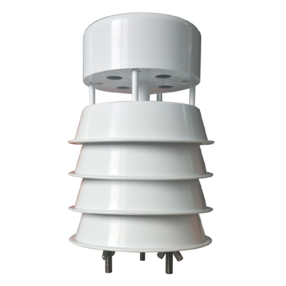 5-in-1 Ultrasonic Weather Station Sensor RS485 | NBL-W-51MUWS
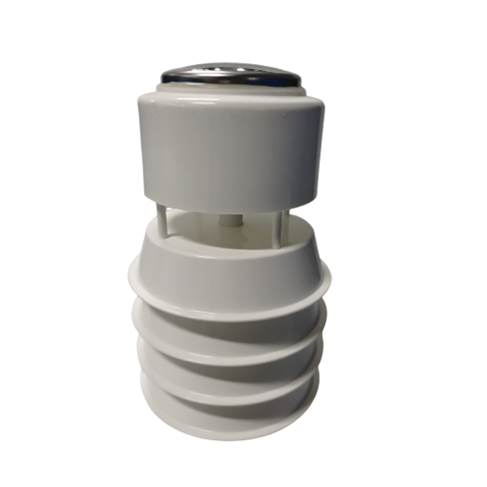 6-in-1 Ultrasonic Weather Station Sensor with Rainfall | NBL-W-61MUWS 7-in-1 Ultrasonic Weather Sensor with Rainfall & illuminance | NBL-W-71MUWS


Screenshot, WhatsApp to identify the QR code
WhatsApp number:+8615367865107
(Click on WhatsApp to copy and add friends)

