





— Blogs —
—Products—
 Consumer hotline +8618073152920
WhatsApp:+8615367865107
Address:Room 102, District D, Houhu Industrial Park, Yuelu District, Changsha City, Hunan Province, China
Product knowledge
Time:2025-11-05 11:55:44 Popularity:1181
Quick Answer: Anemometers for solar and wind energy projects must be selected for their actual duty. A PV weather station observes local operating conditions; a tracker controller needs an approved wind-input and response strategy; wind resource assessment needs representative measurements and a defined uncertainty budget. Cup and ultrasonic instruments can both be useful, but neither technology automatically qualifies a sensor for turbine protection or bankable resource assessment.
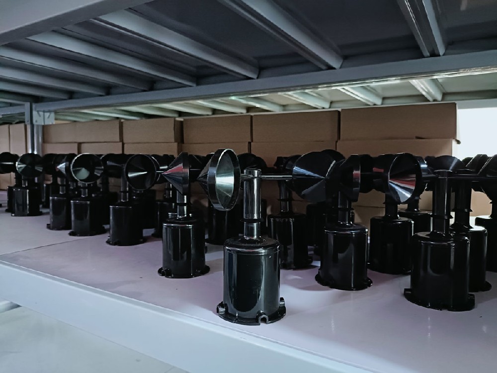
The first question is what changes when the reading changes. A plant-performance analyst may compare wind with module temperature and production. A tracker controller may initiate a stow sequence. A wind developer may use observations to estimate the resource at a proposed turbine location. These applications need different exposure, acquisition and acceptance arrangements even when every display uses m/s.
| Project duty | Useful wind information | What must be defined |
|---|---|---|
| PV weather and performance observations | Local wind alongside irradiance, ambient and module temperatures | Exposure relevant to the array and synchronized records |
| Tracker wind stow input | The wind quantity and timing required by the tracker design | Approved thresholds, averaging, direction needs and response to faults |
| Wind resource assessment | Representative speed and direction observations across the relevant heights and locations | Calibration, mounting effects, data completeness and uncertainty |
A remote dashboard can support all three workflows, but dashboard availability is not the same as a dependable local control input. A delayed cellular upload may still be useful for performance review while being unsuitable for immediate control. Decide where each decision is made before selecting the communications path.
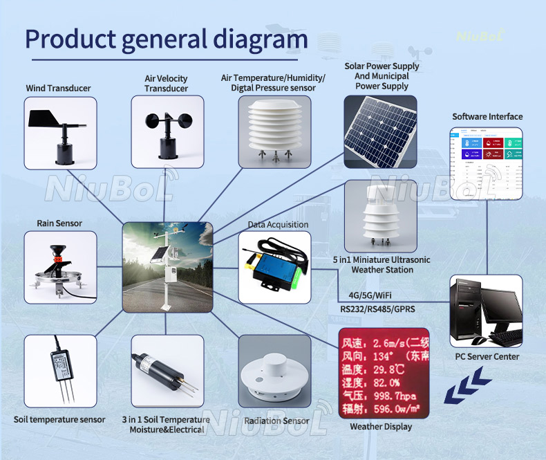
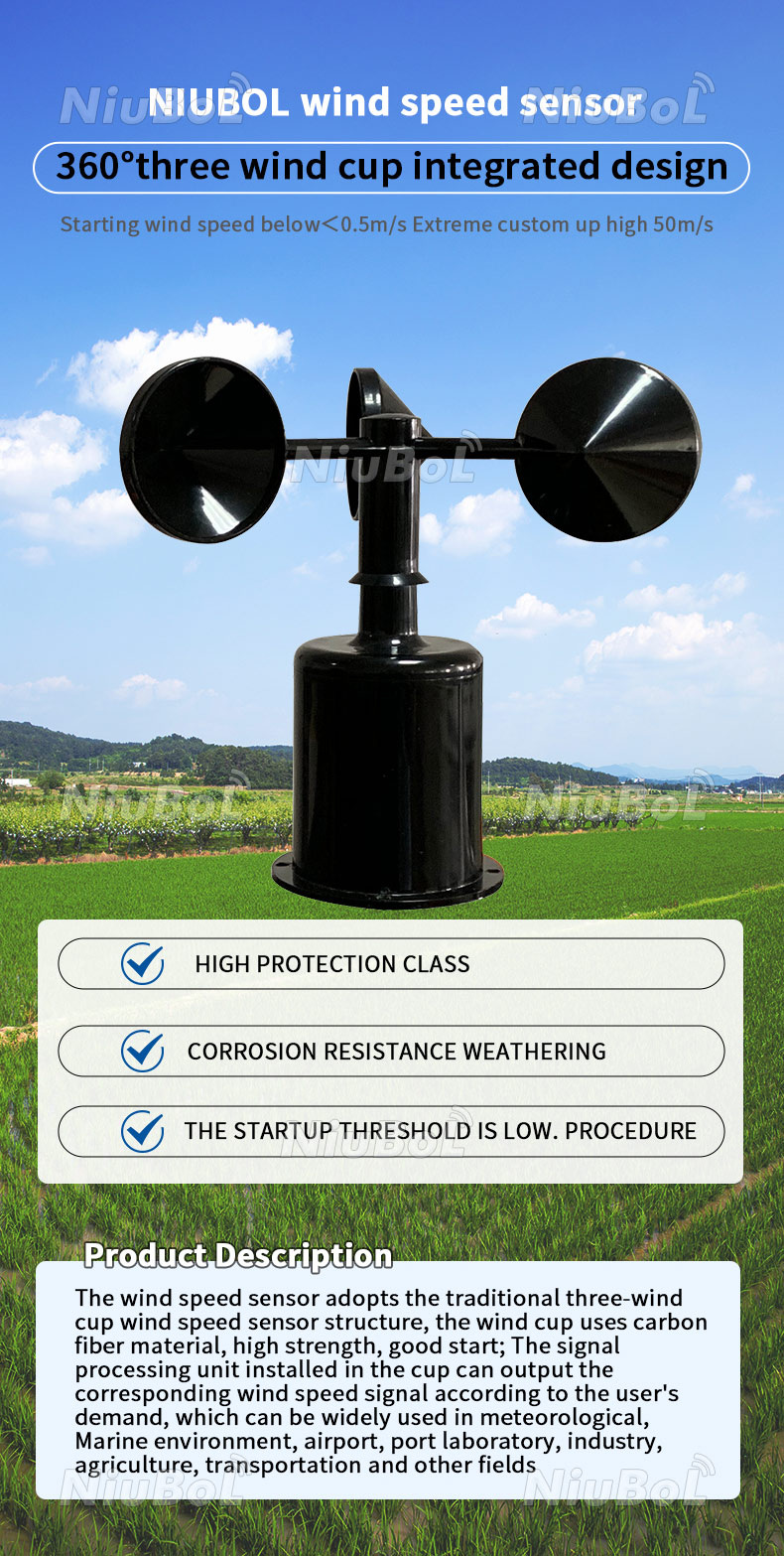
A cup anemometer converts rotor motion into wind speed. It is a practical option for many outdoor observations and can provide pulse, analog or digital outputs, depending on the configuration. Bearings, rotor condition and starting behavior affect its use. A cup rotor does not provide wind direction; add a vane when the project requires that quantity.
A propeller instrument measures flow along its relevant axis and may be combined with a vane to align it with horizontal wind. Its mounting and directional response need to suit the application. It should not be specified as a universally more accurate alternative merely because it looks different from a cup instrument.
An ultrasonic wind sensor calculates air movement from acoustic transit-time differences. A two-dimensional instrument provides horizontal wind information without an external rotating rotor. It still has a measurement path that can be affected by deposits, obstruction or icing. A two-dimensional head should not be described as measuring vertical velocity or a complete three-dimensional turbulence field.
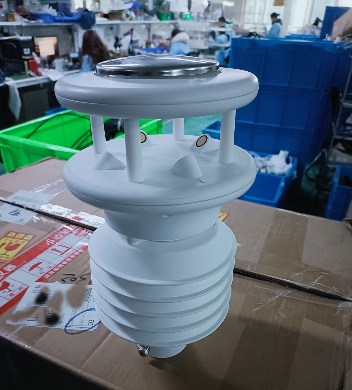
Integrated weather assemblies add other environmental channels around the wind measurement. They can reduce installation wiring for a PV monitoring point, but the selected assembly's wind performance still needs review. A larger channel count is not evidence that the wind measurement is suitable for every energy-project task.
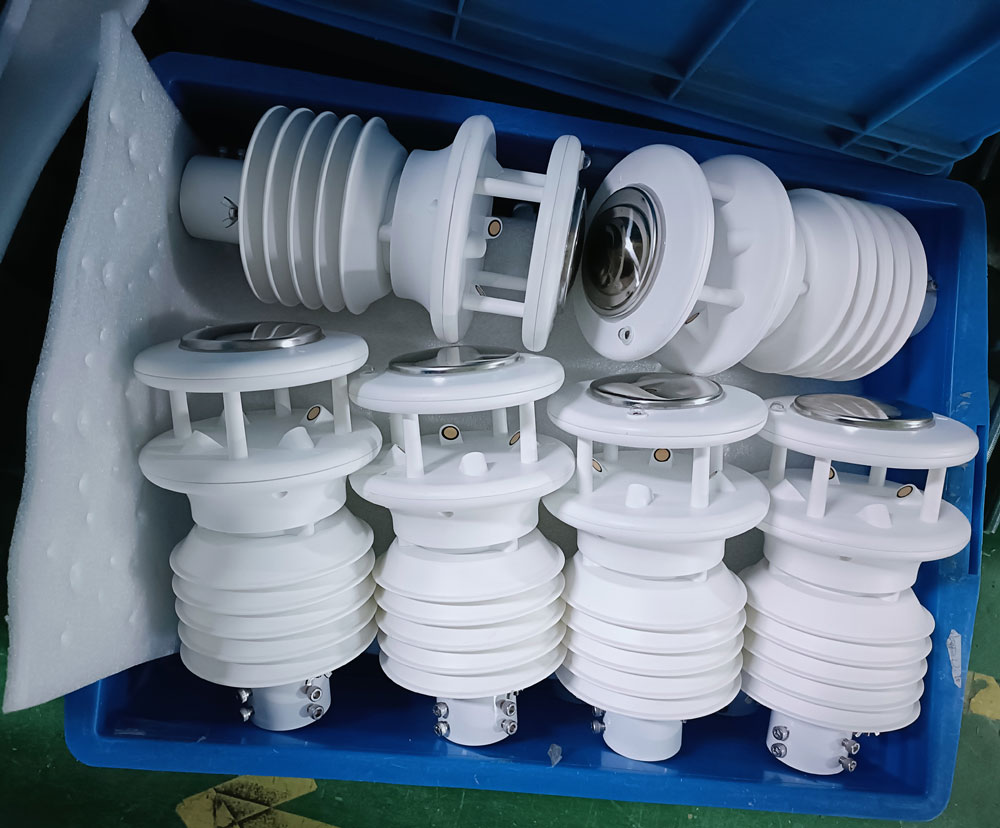
The NBL-W-SS is a separate cup instrument. The NBL-W-21GUWS combines horizontal wind speed and direction in an ultrasonic head. Select the output and specification for the ordered configuration, and keep any wider environmental station's channel list separate from these wind specifications.
| Parameter | NBL-W-SS cup instrument | NBL-W-21GUWS ultrasonic instrument |
|---|---|---|
| Wind speed range | 0-45 m/s or 0-70 m/s option | 0-60 m/s |
| Wind speed accuracy expression | +/-(0.3 + 0.03V) m/s, where V is measured wind speed | +/-(0.5 + 3% FS) m/s; confirm the selected version and FS definition |
| Wind speed resolution | 0.1 m/s | 0.01 m/s |
| Starting wind speed | At most 0.5 m/s | No rotating rotor; confirm the required low-speed reporting behavior |
| Wind direction | Requires a separate direction sensor | 0-359 degrees; accuracy +/-3 degrees; resolution 1 degree |
| Power supply | DC 5 V or DC 12-24 V option | DC 12-24 V |
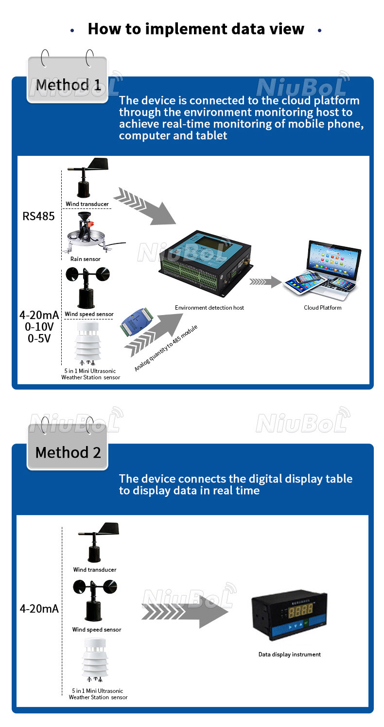
| Output options | Pulse, 4-20 mA, voltage or RS485 by selection | RS485 Modbus configuration |
| Power information | 50 mW nominal | Optional heater rated 3 W; obtain the complete configured load |
| Operating temperature | -40 to +80 degrees C | -20 to +80 degrees C |
| Protection | IP65 | IP65 |
| Cable | 2.5 m standard, other lengths by order | Specify length and exposed cable requirements with the station layout |
For a cup sensor at V = 15 m/s, the stated expression gives +/-0.75 m/s. This is not +/-0.03 of full scale. Conversely, the ultrasonic expression uses FS, not the instantaneous reading. Do not compare the instruments by substituting reading percentage for FS or by treating the number of display decimals as accuracy. Confirm performance against the decision the project needs to make.
For a separate vane, the NBL-W-DS covers 0-360 degrees with accuracy +/-3 degrees and a starting wind speed at most 0.5 m/s. The wind direction sensor is IP65. Its direction channel, mounting orientation and input scaling require their own check; fitting a vane does not add direction to a speed-only register.
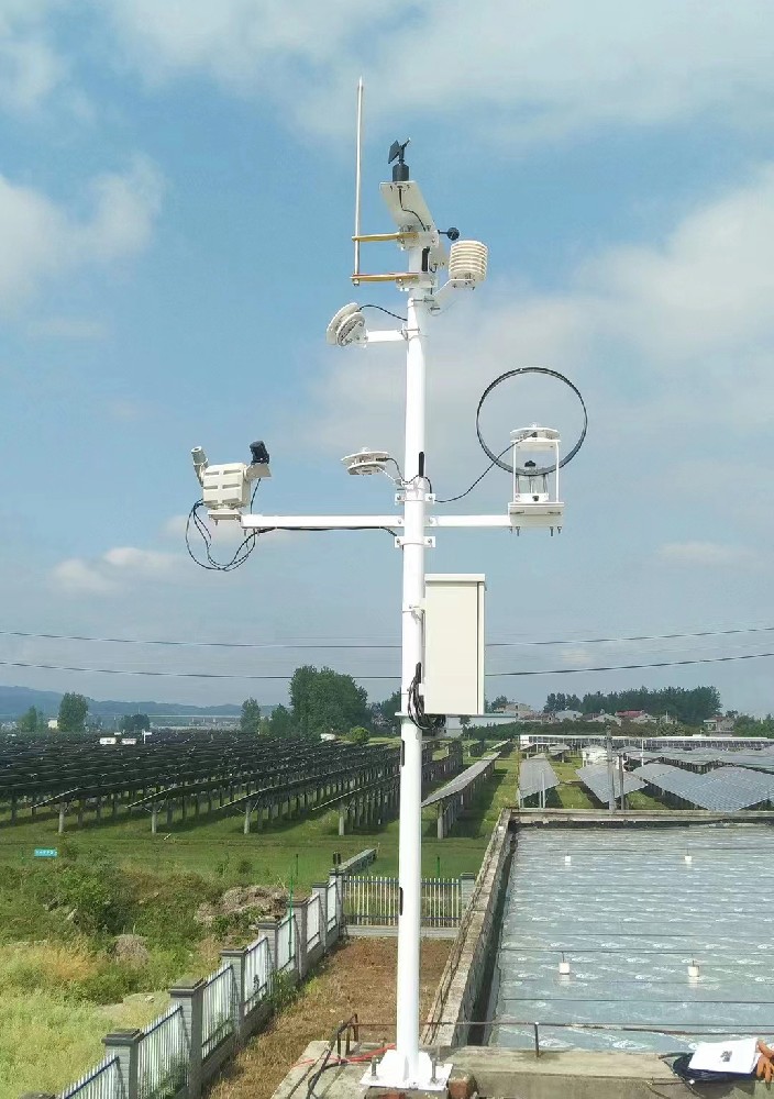
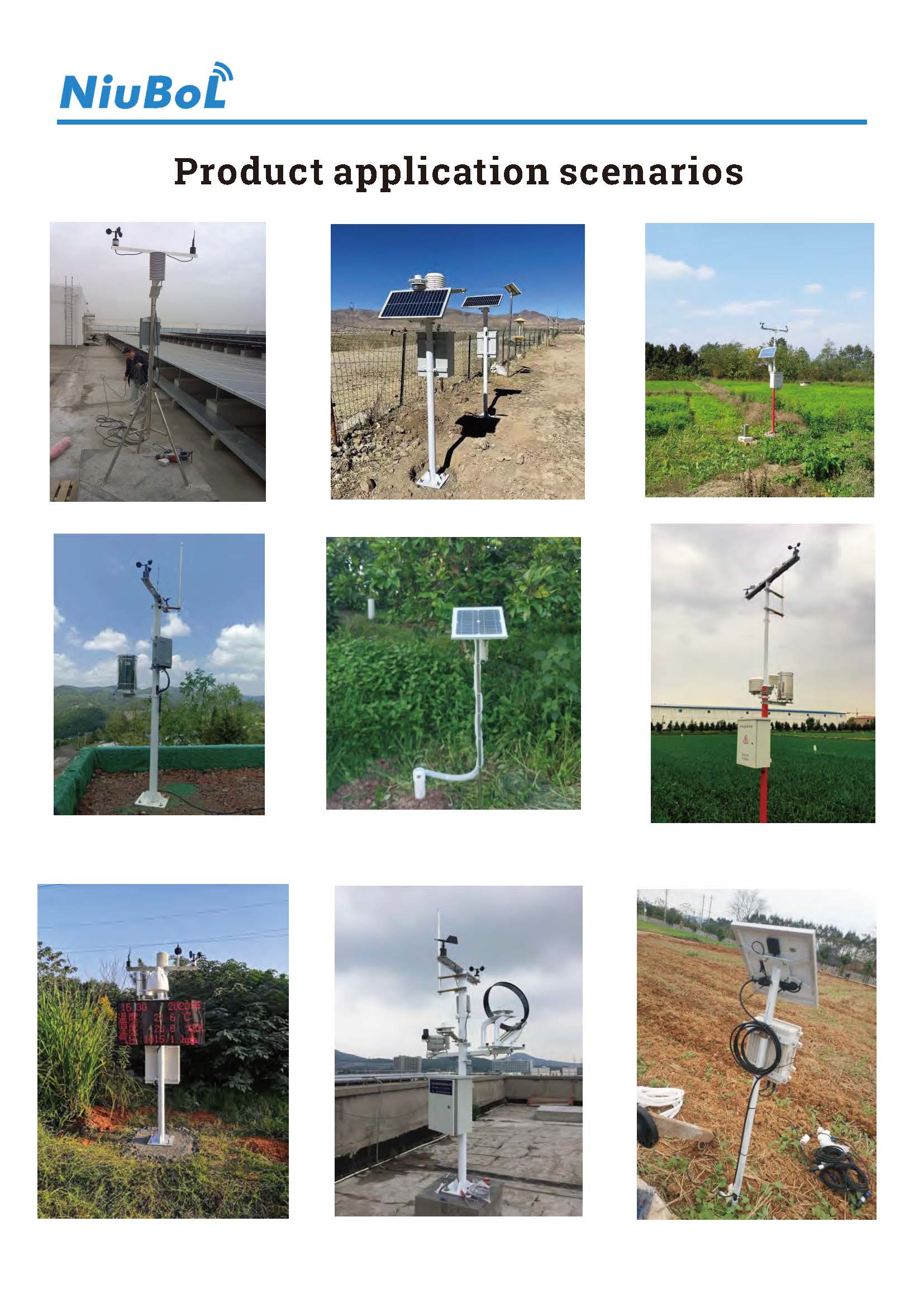
There is no universal rule that every PV anemometer should sit two or three meters above the panels. A measurement intended to represent array-level operating conditions can differ from a conventional open-terrain meteorological observation. Document the height reference, nearby rows and obstructions so later analysts know which exposure the wind channel represents.
Match wind measurements to collector height, and evaluate more than one height or location where wind affects tracked-field operation. These solar-field wind measurement considerations differ from choosing a standard mast height without reviewing the array. Let the plant and tracker requirements determine the layout rather than applying one convenient mast location to a large, uneven site.
Wind resource assessment raises another question: does the measurement describe the wind at the turbine's relevant heights and terrain exposure? A low mast at a solar station cannot be treated as a direct hub-height observation. Height extrapolation and spatial transfer need a suitable assessment method and uncertainty treatment, not a universal multiplier.
For performance analysis, align wind records with irradiance, ambient temperature, backsheet temperature and power data. Wind can help interpret thermal behavior, but it is not the only reason for changes in module temperature or production. A pyranometer remains a radiation instrument; wind data cannot replace its measurement, and neither channel alone establishes the cause of an output loss.
For tracker wind stow, use the tracker manufacturer's accepted input definition. Identify whether the trigger uses a short average, a gust statistic, direction or multiple sensor points. Sampling frequency, internal filtering, polling and controller processing all affect the value that reaches the decision logic. A one-second poll is not proof that the sensor measures an unfiltered one-second gust.
Record the time at the sensor or collector and distinguish it from cloud arrival time. An archive can preserve high-wind events only if the local sampling and storage capture them. Storing occasional snapshots may miss a short event; labeling those snapshots as the period's maximum does not repair the missing information.
With RS485 Modbus RTU, verify addresses, serial settings, register scaling and fault behavior. Keep normal polling separate from setup writes. For an analog configuration, match the selected wind range to the receiving input; a 0-45 m/s transmitter decoded as 0-70 m/s will report an incorrect speed even when the current is correct.
A turbine or tracker should retain its approved protective and operating logic. An additional monitoring station must not bypass it. Define what the controller does if the wind channel is disconnected, frozen or unavailable during maintenance. A readable constant value can be a stale signal rather than calm conditions, so communications success alone is not a complete sensor-health test.
Sensor simulation can check scaling and input logic, while a controlled controller test can check commands and feedback. These checks do not validate the aerodynamic exposure or sensor calibration. Verify the physical measurement and the receiving system separately, then test their combined behavior without exposing operating equipment to an unapproved movement or shutdown.
Inspect cup rotation, rotor damage, mounting stability and cable support on mechanical instruments. For ultrasonic instruments, inspect the acoustic path and deposits. A bearing-free design removes one wear mechanism; it does not eliminate cleaning, verification or access planning. Optional heating also requires power and confirmation of the intended cold-weather performance.
Use IP65 as the wind sensor ingress rating, not proof of icing resistance, salt-fog endurance or the rating of the complete station. Match cable jacket material and UV resistance to exposed runs; cable length alone gives no such information. The cabinet, connectors, mast and lightning-protection arrangement need separate selection.
When requesting NiuBoL wind instruments, identify whether the task is PV observation, an approved control input or wind-resource work. Include the required statistic, range, output, mounting arrangement and verification documents. Ask for a separate price for installation hardware, any heater, calibration work and the collector so the offer matches the measurement task rather than only a sensor name.
No. Compare the specified performance, calibration and installed exposure of the particular instruments. Removal of a rotating rotor does not establish lower uncertainty for every task. Percentage-of-reading and percentage-of-full-scale specifications must also be distinguished.
Only through an approved design with a compatible wind input and tested logic. The tracker requirements determine thresholds, timing and fault response. A general monitoring dashboard should not be assumed to provide the required protective function.
Not by itself. Tracker geometry, direction, operating strategy and structural design affect the required response. Use the accepted tracker instructions rather than deriving a universal angle from an isolated wind-speed reading.
It is a measurement at its installed height and exposure. Transferring it to hub height needs a justified assessment approach. A general-purpose sensor's range or RS485 output does not establish a resource-assessment certification.
Establish the required geographic reference, align and secure the instrument to that reference, and check the decoded direction. Account for magnetic declination if using a compass. Do not equate magnetic north with true north at every location.
Resolution alone is insufficient. Evaluate accuracy, starting or low-speed behavior, filtering and the required statistic at that threshold. Additional decimal places do not make uncertainty disappear.
Check identity and ordered range, measurement verification, mast exposure, direction reference, decoding, timestamps and the receiving system's fault response. Where control is involved, test the approved command and feedback sequence under a safe commissioning procedure.
Use the project's uncertainty requirements, environment, instrument condition and comparison history to set the interval. A fixed one- or two-year statement is not appropriate for every energy installation, and a visual inspection does not replace calibration when it is required.
Select anemometers for solar and wind energy projects by the decision they support. PV observations, tracker inputs and wind-resource measurements need different exposure and acceptance arrangements. Match the cup or ultrasonic configuration to that duty, preserve the meaning of the wind statistic and verify the complete route into the receiving system.
 NBL-W-21GUWS-Ultrasonic-Wind-speed-and-direction-Sensor.pdf
Prev:Best Solar Irradiance Meters for PV System Monitoring
Next:Automatic Weather Station Selection: Resolve Conflicting Requirements
Related recommendations
Sensors & Weather Stations Catalog
Agriculture Sensors and Weather Stations Catalog-NiuBoL.pdf
Weather Stations Catalog-NiuBoL.pdf
Agriculture Sensors Catalog-NiuBoL.pdf
Water Quality Sensor Catalog-NiuBoL.pdf
Related products
 Combined air temperature and relative humidity sensor
 TDR Soil Moisture & Temperature Sensor for irrigation| RS485 |4-20mA| NBL-S-THR
 Soil pH sensor RS485 soil Testing instrument soil ph meter for agriculture |NBL-S-PH
 Wind Speed sensor Output Modbus/RS485/Analog/0-5V/4-20mA
 Tipping bucket rain gauge for weather monitoring auto rainfall sensor RS485/Outdoor/stainless steel
 Pyranometer Solar Radiation Sensor 4-20mA/RS485


Screenshot, WhatsApp to identify the QR code
WhatsApp number:+8615367865107
(Click on WhatsApp to copy and add friends)

