

— Products —
 Consumer hotline +8618073152920
 WhatsApp:+8615367865107
Address:Room 102, District D, Houhu Industrial Park, Yuelu District, Changsha City, Hunan Province, China
Agricultural Sensors
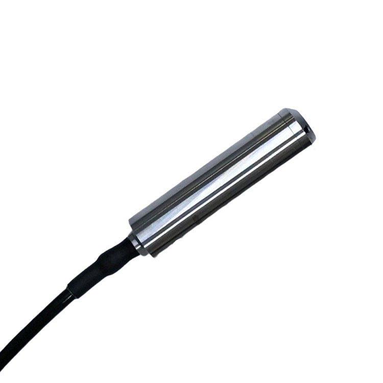
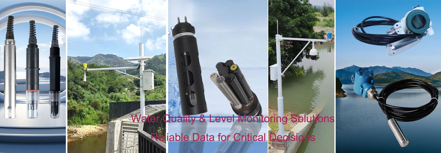
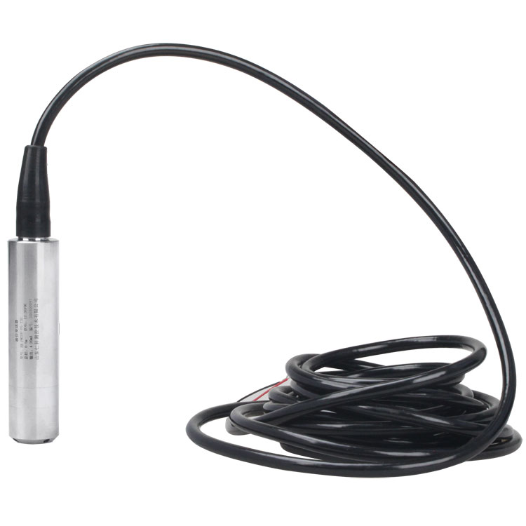
NBL-L-WLPS submersible water level transmitter uses a diffused silicon pressure sensor with IP68 protection and RS485 Modbus for tanks, wells, rivers, reservoirs and irrigation.
Tel/WhatsApp:+8615367865107
Email:Arvin@niubol.com +Nearly 100 partner companies in more than 75 countries. We are committed to providing high-quality, practical products to meet your needs and help you solve problems. Our products comply with international standards and are certified with ISO, CE and RoHS.Product Details
The NiuBoL NBL-L-WLPS Submersible Water Level Transmitter is an IP68 hydrostatic level sensor designed for continuous liquid-level measurement in tanks, wells, reservoirs, rivers, irrigation systems, industrial pools and other water or liquid monitoring applications.
The transmitter uses a diffused silicon piezoresistive sensing element. The probe is immersed directly in the measured liquid, where hydrostatic pressure changes according to the liquid level. An internal signal-processing circuit converts the pressure measurement into digital level data for transmission through RS485 Modbus RTU.
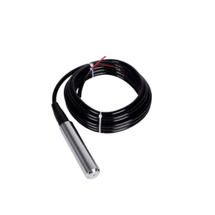
A vent tube inside the special cable connects the reference side of the pressure sensor to atmospheric pressure, helping compensate for atmospheric-pressure changes. The stainless-steel probe, protective cap, anti-clogging liquid inlet and sealed cable structure are designed for long-term submerged measurement.
| Model | NBL-L-WLPS |
| Product Name | Submersible Water Level Transmitter |
| Measurement Principle | Diffused Silicon Piezoresistive / Hydrostatic Pressure |
| Measurement Range | Selectable according to project requirements; custom ranges available |
| Accuracy Class | 0.5 standard; optional 0.2 / 0.1 |
| Power Supply | DC 10–30 V, typical 24 V |
| Maximum Power Consumption | 0.2 W |
| Output | RS485 |
| Protocol | Modbus RTU |
| Default Baud Rate | 4800 bps |
| Configurable Baud Rate | 1200–115200 bps |
| Default Device Address | 0x01 |
| Maximum RS485 Distance | Up to 2000 m under suitable RS485 wiring conditions |
| Protection Rating | IP68 |
| Probe Diameter | Ø26.8 mm |
| Sensor Element Temperature | -40 to +80°C |
| Measured Medium | Water, oil and other liquids non-corrosive to stainless steel |
| Long-Term Medium Temperature | ≤60°C |
| Sampling Rate | 2400 samples/s |
| Long-Term Stability | ±0.2%FS/year |
| Overload Specification | <1.5 × full scale |
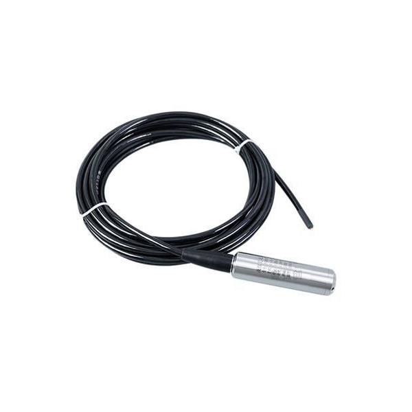
When the probe is submerged below the liquid surface, the pressure-sensitive diaphragm detects the hydrostatic pressure generated by the liquid column above the sensing point.
For a liquid with known density, hydrostatic pressure is related to level by:
P = ρgh
| P | Hydrostatic pressure at the sensing diaphragm |
| ρ | Density of the measured liquid |
| g | Gravitational acceleration |
| h | Liquid level above the sensor diaphragm |
The diffused silicon sensor converts this pressure into an electrical signal. The built-in microprocessor and signal-processing circuit then calculate the level value and transmit it through the RS485 Modbus interface.
The NBL-L-WLPS uses a special cable containing an internal atmospheric vent tube. This tube allows the reference side of the pressure sensor to remain connected to atmospheric pressure.
This is important because atmospheric pressure changes independently of the water level. Atmospheric compensation allows the transmitter to determine the pressure produced primarily by the liquid column rather than treating atmospheric-pressure changes as level changes.
| Do Not Seal the Vent | Do not clamp the cable so tightly that the internal vent tube becomes blocked. |
| Avoid Sharp Bends | Sharp cable bends can restrict the atmospheric vent path. |
| Protect the Vent End | Keep the atmospheric vent outlet facing downward and protected from rainwater and condensation. |
| Protect the Cable | Avoid cutting, puncturing, crushing or damaging the vented cable. |
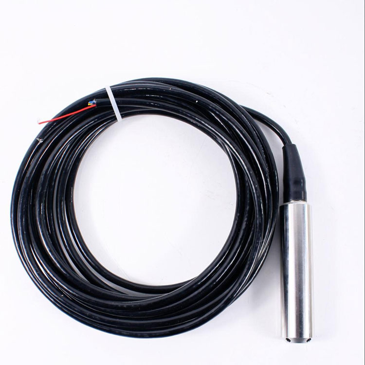
| Diffused Silicon Sensor | Piezoresistive pressure sensing provides continuous hydrostatic liquid-level measurement. |
| IP68 Submersible Design | Designed for continuous immersion in suitable water and liquid applications. |
| Automatic Correction Algorithm | Helps reduce numerical fluctuations caused by short-term water-surface movement. |
| Sloped Liquid Inlet | Designed to reduce direct entry of sediment and impurities and improve impact resistance around the diaphragm area. |
| Electrical Protection | Includes reverse-polarity protection and transient overcurrent / overvoltage protection. |
| Wide Power Supply | DC 10–30 V input, with 24 VDC as the typical supply. |
| RS485 Modbus | Suitable for PLCs, RTUs, data loggers, industrial controllers and IoT gateways. |
The NBL-L-WLPS is not limited to one fixed 1000 mm range. Different full-scale ranges can be selected according to the actual liquid depth, and customized ranges are available for special projects.
| Selection Item | Available Configuration |
|---|---|
| Measurement Range | Select according to required liquid-level range; customized ranges available |
| Standard Accuracy Class | 0.5 |
| Optional Accuracy Classes | 0.2 / 0.1 |
| Communication | RS485 Modbus RTU |
For product selection, specify the expected minimum and maximum liquid level, measured medium, medium temperature, cable length and required accuracy class.
The NBL-L-WLPS can be installed vertically, inclined or horizontally depending on the tank, channel or monitoring structure. The sensing end must remain exposed to the measured liquid and should not become buried in sediment.
| Vertical Installation | Commonly used in tanks, wells, reservoirs and still-water level monitoring. |
| Inclined Installation | Can be used when the structure does not allow direct vertical suspension. |
| Horizontal Installation | Permitted when the sensing opening remains exposed and free from sediment blockage. |
| High Water Movement | Fix the probe securely or add a suitable weight when water movement could cause excessive probe motion. |
| Sediment | Do not allow mud, sand or other deposits to bury or block the sensing end. |
Two cable-color configurations are documented for the RS485 version. Always follow the wire identification supplied with the actual sensor.
| Function | Cable Version A | Cable Version B |
|---|---|---|
| Power + | Red | Brown |
| Power - | Blue | Black |
| RS485 A | Yellow | Yellow |
| RS485 B | White | Blue |
Important: When several RS485 devices share one bus, each device must use a unique Modbus address.
| Protocol | Modbus RTU |
| Encoding | 8-bit binary |
| Data Bits | 8 |
| Parity | None |
| Stop Bits | 1 |
| Error Check | CRC-16 |
| Default Baud Rate | 4800 bps |
| Configurable Baud Rate | 1200–115200 bps |
| Default Address | 0x01 |
| Read Register Function | 0x03 / 0x04 depending on register |
| Write Single Register | 0x06 |
| Register | PLC Address | Function | Supported Code |
|---|---|---|---|
| 0002H | 40003 | Unit type: 9 = m, 10 = cm, 11 = mm | 0x03 / 0x04 |
| 0003H | 40004 | Decimal places | 0x03 / 0x04 |
| 0004H | 40005 | Measured level output | 0x03 / 0x04 |
| 0005H | 40006 | Range zero point | 0x03 / 0x04 / 0x06 |
| 0006H | 40007 | Range full-scale point | 0x03 / 0x04 / 0x06 |
| 000CH | 40013 | Offset value | 0x03 / 0x04 / 0x06 |
For example, for a 0–3 m level transmitter configured with three decimal places, if register 0004H returns decimal value 101:
101 × 10-3 = 0.101 m
The actual decimal position and engineering unit should be read from the relevant Modbus registers rather than assuming one fixed scaling value for every measuring range.
| Water Treatment Plants | Wastewater Treatment | Municipal Water Supply |
| Water Tanks | Water Wells | Geothermal Wells |
| Reservoirs | Rivers | Hydrological Monitoring |
| Industrial Tanks | Oil Tanks | Agricultural Irrigation |
| Mine Water Level | Groundwater Monitoring | Marine Applications |
| Problem | Check |
|---|---|
| Cannot Connect to PLC / PC | Check COM port selection, USB-to-RS485 driver and converter status. |
| No Modbus Response | Check device address, baud rate, data bits, parity and stop-bit settings. |
| Multiple Sensors Conflict | Confirm that no two devices on the RS485 bus use the same address. |
| Communication Failure | Check for an open RS485 line or reversed A/B communication wires. |
| Long RS485 Network | Use proper RS485 wiring, nearby power where appropriate, repeaters when required and suitable 120 Ω termination. |
| Unstable Level Reading | Check whether the probe is moving excessively in turbulent liquid and secure or weight the probe if necessary. |
| Incorrect Level Reading | Check that the pressure inlet is not buried or blocked by sediment and that the atmospheric vent tube remains open. |
| Sensor Diaphragm | Do not touch the diaphragm with sharp tools or foreign objects. |
| Probe Protection | Avoid strong impact, dropping or unauthorized disassembly. |
| Sediment Inspection | Check periodically that the liquid inlet and sensing area are not blocked by sediment or debris. |
| Vented Cable | Inspect for crushing, punctures, sharp bending or other damage that could block atmospheric compensation. |
| Electrical Wiring | Confirm wiring before applying power. Incorrect wiring can damage the internal electronics. |
A1. It uses a diffused silicon piezoresistive pressure sensor to determine liquid level from hydrostatic pressure.
A2. No. Different measuring ranges can be selected according to project requirements, and customized ranges are available.
A3. The supported DC supply range is 10–30 V, with 24 VDC as the typical supply.
A4. The default baud rate is 4800 bps. The communication baud rate can be configured from 1200 to 115200 bps.
A5. The factory default address is 0x01. Each sensor should be assigned a unique address when multiple devices share one RS485 network.
A6. The vent tube provides atmospheric-pressure compensation for the gauge-pressure sensing element. It must remain open and protected from water ingress.
A7. It can be used with water, oil and other liquids that are non-corrosive to stainless steel. For continuous measurement, the source specification limits medium temperature to 60°C or below.
A8. Yes. Vertical, inclined and horizontal installation are supported, provided that the sensing end is exposed to the liquid and is not blocked or buried by sediment.
A9. The transmitter specification states communication distances up to 2000 m. Actual performance depends on cable type, topology, interference, baud rate, termination, power supply and field conditions.
A10. Yes. The RS485 Modbus transmitter can connect to a compatible RTU, data logger or IoT gateway, which can then transmit the measurement data through 4G, Ethernet, Wi-Fi, LoRaWAN or other supported communication systems.
The NBL-L-WLPS Submersible Water Level Transmitter combines a diffused silicon pressure sensor, IP68 submerged construction, vented atmospheric-reference cable and RS485 Modbus communication for continuous water and liquid-level monitoring.
When selecting the transmitter, specify the required measuring range, measured medium, cable length, accuracy class, installation conditions and communication requirements so the sensor can be configured for the application.
Sensors & Weather Stations Catalog
 Agriculture Sensors and Weather Stations Catalog-NiuBoL.pdf
Weather Stations Catalog-NiuBoL.pdf
Agriculture Sensors Catalog-NiuBoL.pdf
Water Quality Sensor Catalog-NiuBoL.pdf
Related recommendations
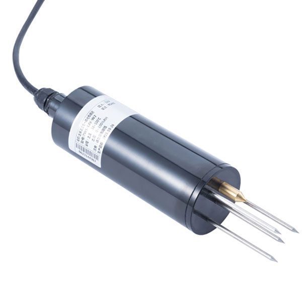 TDR Soil Moisture & Temperature Sensor for irrigation| RS485 |4-20mA| NBL-S-THR
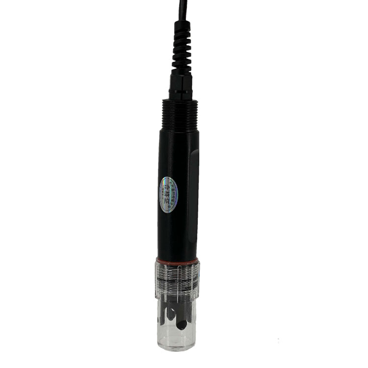 Soil pH sensor RS485 soil Testing instrument soil ph meter for agriculture |NBL-S-PH
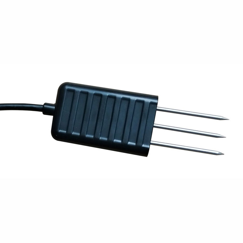 Soil NPK Sensor RS485 Modbus | NBL-S-NPK | NiuBoL
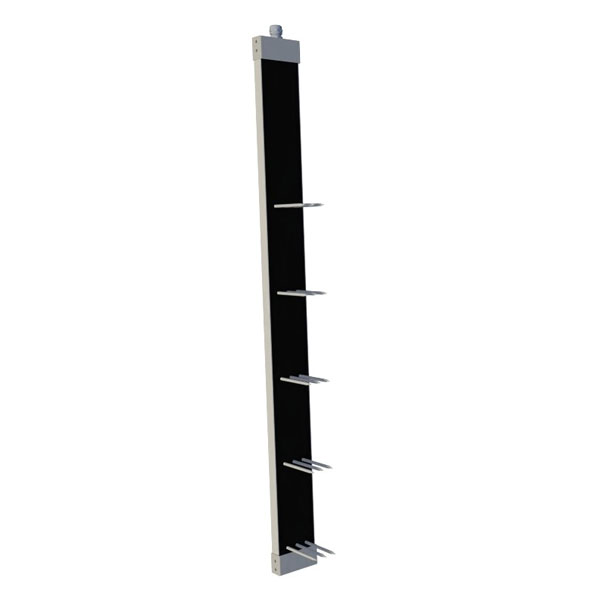 NBL-S-TM-MD Multi-Layer Soil Moisture Temperature Salinity Sensor | RS485 Modbus
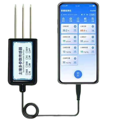 7-in-1 Soil Sensor for Android USB-Type-C
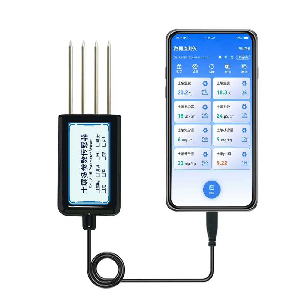 8-in-1 Portable Soil Sensor for Android Type-C/USB Soil Multi-Parameter Tester & Analyzer

Screenshot, WhatsApp to identify the QR code
WhatsApp number:+8615367865107
(Click on WhatsApp to copy and add friends)