





— Blogs —
—Products—
 Consumer hotline +8618073152920
WhatsApp:+8615367865107
Address:Room 102, District D, Houhu Industrial Park, Yuelu District, Changsha City, Hunan Province, China
Product knowledge
Time:2025-09-08 14:38:10 Popularity:1225
IoT agriculture sensor networks should connect measurements to identifiable field zones, depths and devices. Several compatible probes can share a local acquisition system, but matching RS485 terminals alone is not enough. Plan power, polling, output decoding and replacement procedures for each zone, then choose how those zones reach the farm platform. A larger network should preserve measurement context as it grows.
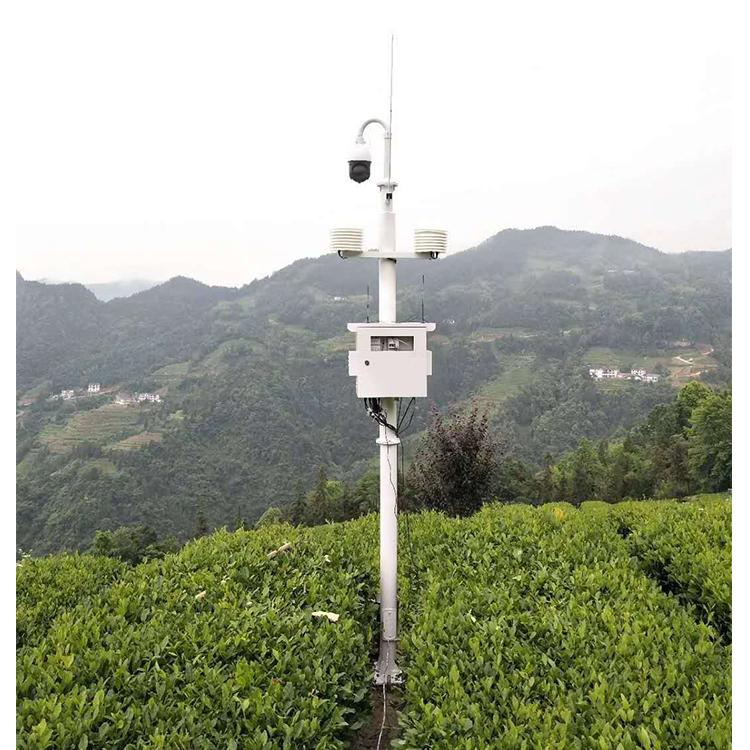
A farm dashboard needs more than a list of values. Soil moisture from one depth and irrigation block cannot be interpreted as moisture from every part of the farm. Before choosing gateways, define each point's zone, depth or height, measured channels, device model and service location.
As an illustrative label, "Block A, root zone, 20 cm" contains information that "Sensor 03" does not. The final naming scheme should also identify the actual probe and any replacement. Keep physical identity separate from a communications address, because addresses may be reused on separate buses or reassigned during maintenance.
| Schedule item | Why it belongs in the design |
|---|---|
| Zone and depth or height | Links the measurement to the crop or soil condition being assessed |
| Model and output version | Determines the required input and power connection |
| Bus and device address | Prevents conflicts while allowing separate local networks |
| Channel, unit and scaling | Prevents a valid packet from becoming a wrongly interpreted value |
| Sampling requirement | Sets acquisition capacity independently of dashboard refresh |
| Service access | Allows isolation, checks and replacement without guessing which point is affected |
Within one greenhouse or equipment area, a wired bus can collect several compatible sensors with limited cabling. Across separated irrigation blocks, independent acquisition points may be easier to power and service. Evaluate actual routes and ground conditions rather than choosing the topology from farm area alone.
Long shared routes introduce power drop, surge exposure and fault-location work. Segmenting the farm can limit the scope of a local fault only if the electrical and acquisition design actually separates those segments. Merely assigning different dashboard names does not isolate a cable short.
Wireless field links can avoid some cable routes, but every field node still needs energy and a maintainable antenna arrangement. A buried probe is not automatically a buried radio. Select and test the node position, including the real enclosure and crop growth around it, without assuming a fixed distance or nationwide cellular availability.
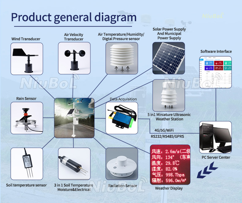
The NiuBoL NBL-S-THR measures soil moisture and temperature and has different output versions. The NBL-S-TMC adds an EC channel through RS485 Modbus RTU. The NBL-W-LBTH measures air temperature, humidity and pressure. They do not use one interchangeable channel definition.
| Example device | Connection requirement | Design check |
|---|---|---|
| NBL-S-THR | DC 12-24 V; RS485, 4-20 mA or voltage version | Order the output that matches the acquisition input |
| NBL-S-TMC | RS485 Modbus RTU; DC 5-24 V or 12-24 V by configuration | Map temperature, moisture and EC separately |
| NBL-W-LBTH | RS485 Modbus RTU version; DC 12-24 V; at least 1000 ms between communications | Respect device timing and atmospheric channel units |
| TG462 / TG462S | 3 RS485 ports; analog input configuration available | Allocate ports and input types, then check the required acquisition software |
Request the register map and electrical details for each delivered version. Two probes can both return a moisture number but use different registers, scales or signed-value handling. Keep the input configuration with the model and firmware record, not just with a cable color note.
A shared serial master normally services requests in sequence. Its scan time includes response delays, communication timing, retries and timeouts. An illustrative schedule allowing two seconds for each of twelve devices already consumes 24 seconds before additional work. It cannot provide a complete new scan every ten seconds.
Define what happens when one device stops responding. Repeated long timeouts can delay healthy devices on the same polling schedule. Configure and test the acquisition behavior so a disconnected probe does not make an entire zone appear frozen. Required intervals may justify separate ports or acquisition points.
For power-switched nodes, include sensor startup and stabilization in the sampling cycle. A low radio sleep current does not describe the whole node's consumption. The probe, converter, logger and transmission load must all be included in the power design, with voltage verified at the field device.
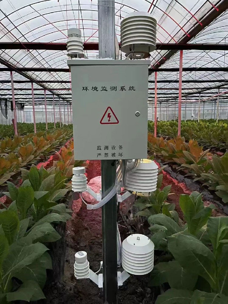
Commission a small representative group before expanding. Check the final zone name, depth, channel unit and timestamp against the field schedule. A plausible moisture trend is insufficient if it belongs to the neighboring irrigation block.
When adding a node, allocate device addresses on its actual local bus. The same address can be used on electrically separate buses if the host maintains distinct identities; it cannot be duplicated among devices that answer the same master on one bus. Check that platform identifiers remain unique across all collectors.
After replacing a probe, verify its output version and defaults before connecting it to the production network. A replacement that arrives at a default address can conflict with an installed unit. Record the old and new serial identities and recheck the affected dashboard channel rather than silently continuing under the old hardware identity.
Remote observations can support an irrigation decision without directly controlling a valve. If automation is required, define which local controller makes the decision, what data it uses and how it responds to a missing or implausible input. A cloud display does not establish those control functions.
Test safe behavior with actuators isolated before enabling automatic operation. A stale moisture value must not be treated as a new observation. Neither a communications connection nor a sensor threshold proves that the pump, valve and irrigation distribution deliver the intended water volume.
Use crop and soil conditions to establish control thresholds; the network does not make one percentage suitable for every zone. The soil moisture accuracy and field-check guide explains why units, contact and representative depth matter before control logic is applied.
Provide a zone map, sensor schedule, actual cable routes, power sources, desired acquisition interval and the final platform interface. Identify areas without verified radio or cellular service. A supplier can then distinguish local wired collection, separate wireless nodes and the onward network equipment needed.
The TG462 / TG462S collector can be evaluated for mixed local inputs, while other arrangements may suit distributed nodes. Confirm the regional modem and project software separately. Network, subscription and integration costs should be listed alongside hardware; a per-sensor price does not represent an installed farm network.
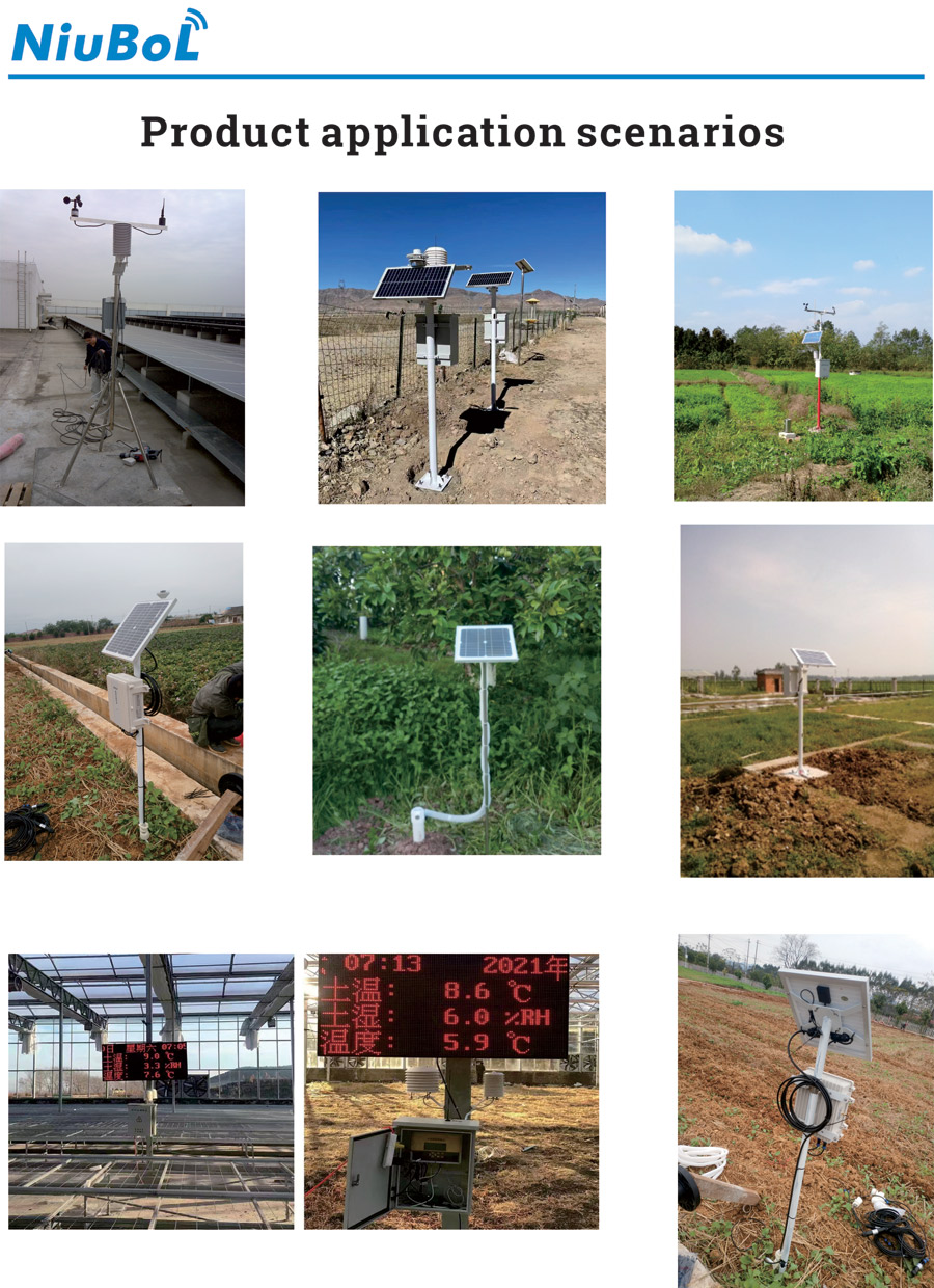
Only compatible devices within the electrical, timing and loading limits of the design should share a bus. They need unique addresses, matching serial settings and correct register decoding. Evaluate cable routes and power drop rather than assuming farm-wide coverage from the interface name.
Not necessarily. One acquisition point can read several compatible nearby probes. Separate points may be appropriate for distant zones, independent power or fault isolation. Base the choice on layout and service requirements, not on a universal sensor-to-gateway ratio.
Check address conflicts, serial settings, supply loading and the polling timeout. A device that repeatedly fails to answer can consume the scan budget. Test it alone, then reintroduce it under controlled conditions.
No. Automatic operation requires appropriate local or remote control logic, actuator interfaces, interlocks and fault behavior. Validate measurement meaning and irrigation delivery as well as data transport before enabling control.
Check supply, output version, address, serial parameters, channel units and physical location. Confirm the final platform value and record the replacement identity. Do not assume a matching housing means identical electrical or software configuration.
Begin with a site communications survey and the required service level. Evaluate a suitable local link, separate backhaul or another service with actual equipment testing. No listed technology guarantees availability, latency or operating cost at every farm.
IoT agriculture sensor networks should retain the relationship between each reading and its field zone as devices are added or replaced. Build the zone schedule first, then verify local inputs, power and scan capacity. This makes expansion and fault finding manageable without mistaking more connected devices for more useful agricultural information.
Prev:Role of Agricultural Weather Stations in Precision Farming
Next:Using Digital Humidity and Temperature Sensors in Greenhouses for Optimal Crop Growth
Related recommendations
Sensors & Weather Stations Catalog
 Agriculture Sensors and Weather Stations Catalog-NiuBoL.pdf
Weather Stations Catalog-NiuBoL.pdf
Agriculture Sensors Catalog-NiuBoL.pdf
Water Quality Sensor Catalog-NiuBoL.pdf
Related products
 Combined air temperature and relative humidity sensor
 TDR Soil Moisture & Temperature Sensor for irrigation| RS485 |4-20mA| NBL-S-THR
 Soil pH sensor RS485 soil Testing instrument soil ph meter for agriculture |NBL-S-PH
 Wind Speed sensor Output Modbus/RS485/Analog/0-5V/4-20mA
 Tipping bucket rain gauge for weather monitoring auto rainfall sensor RS485/Outdoor/stainless steel
 Pyranometer Solar Radiation Sensor 4-20mA/RS485


Screenshot, WhatsApp to identify the QR code
WhatsApp number:+8615367865107
(Click on WhatsApp to copy and add friends)

