





— Blogs —
—Products—
 Consumer hotline +8618073152920
WhatsApp:+8615367865107
Address:Room 102, District D, Houhu Industrial Park, Yuelu District, Changsha City, Hunan Province, China
Product knowledge
Time:2026-08-21 09:07:00 Popularity:241
Quick Answer: If a digital pH water quality tester reads correctly through one interface but incorrectly in a PLC, trace the returned data before recalibrating the electrode. For the described NBL-WQ-PH register layout, pH and temperature are separate integer-and-decimal pairs, not two floating-point numbers. Verify the address convention, four-register read and scaling, then test stale-data handling.
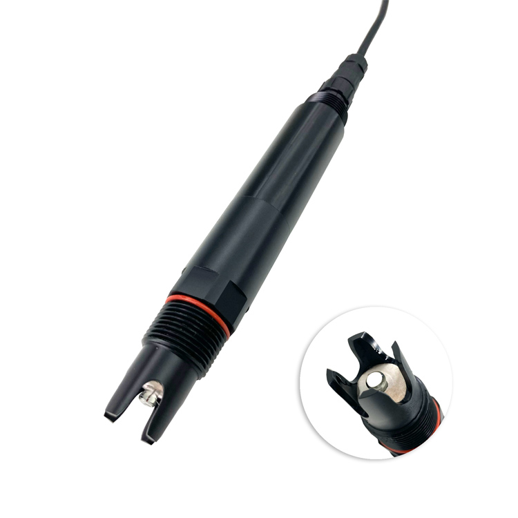
A digital pH instrument combines an electrode measurement with an electronic output. The receiving system must still interpret that output correctly. A wrong PLC value can come from an incorrect register offset, a decimal conversion or an old value retained after communication fails. Changing calibration to correct a host-display problem alters the measurement without fixing the data path.
Compare a direct read of the probe with the PLC or data logger while the water or verification condition is stable. Retain the returned register words, decoded pH, decoded temperature and acquisition time. This gives the technician a repeatable starting point instead of two screenshots whose underlying data are unknown.
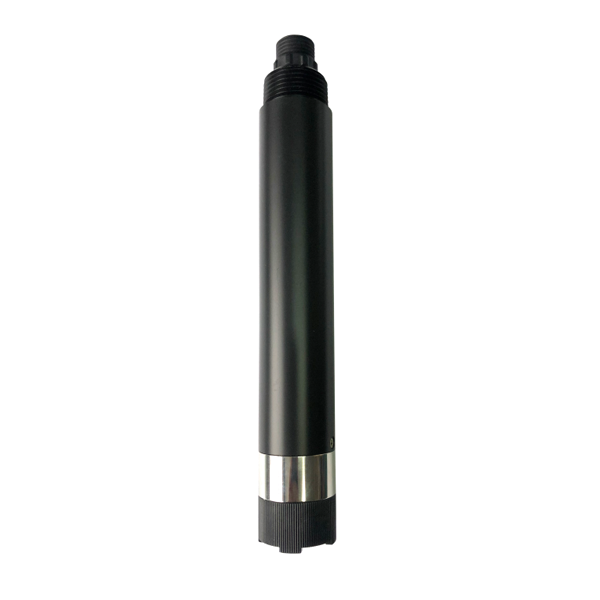
Other probes, such as the dissolved oxygen instrument shown here, can use different data definitions even when their connectors and RS485 leads look similar. Do not copy a working oxygen tag into the pH channel without verifying the pH-specific layout.
The NBL-WQ-PH online pH sensor provides RS485 Modbus RTU. It is not a bare millivolt electrode that can be connected to an ordinary voltage input. Keep its field supply, serial electrical interface and measurement registers distinct when reviewing an existing panel.
| Item | RS485 NBL-WQ-PH configuration | Check at the receiving system |
|---|---|---|
| Measurement | 0-14 pH; 0.01 pH resolution; stated accuracy +/-0.1 pH | A plausible decimal display does not prove the right data source |
| Probe supply | 12-24 V DC; 0.2 W at 12 V | Verify voltage at the probe under operating load |
| Serial interface | RS485 / Modbus RTU | Use a compatible RS485 port or interface module |
| Default serial settings | 9600 baud, 8 data bits, no parity, 1 stop bit | Match the delivered settings; previously configured devices may differ |
| Default device address | 3 | Identify the actual address and avoid duplicates on a shared bus |
| Measurement read | Function 03; protocol start 0x0000; four 16-bit registers | Expect eight measurement-data bytes in a normal response |
| Probe environment | 0-65 degrees C; pressure below 0.2 MPa; IP68 | Do not treat a communications repair as proof of process suitability |
| Standard assembly | POM housing; 3/4 NPT immersion mounting; 5 m cable | Keep joints dry and protected without pulling on the cable |
For the described four-wire cable, red is supply positive, black is GND, blue is 485A and white is 485B. Confirm the supplied identification before energising. A different connector or optional interface needs its own wiring definition; matching conductor colours between unrelated instruments is not sufficient.
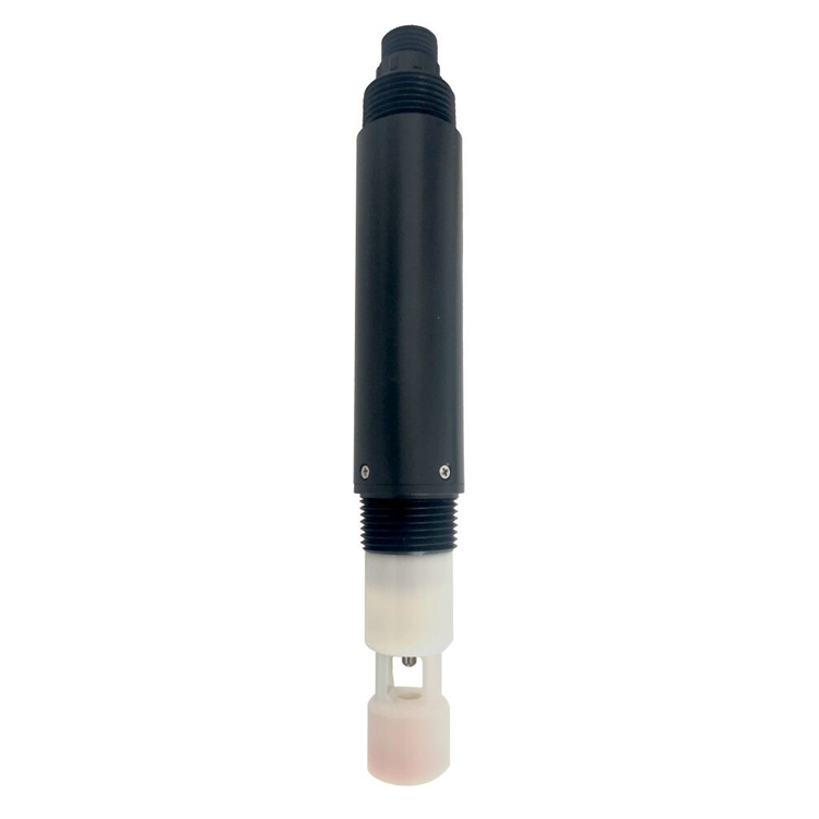
In this layout, the first word contains the pH integer and the second contains its number of decimal places. The third and fourth words do the same for temperature. Apply each decimal count to its associated value. Do not combine every two words into an IEEE floating-point value merely because another sensor uses that format.
| Illustrative register | Returned value | Interpretation |
|---|---|---|
| Protocol offset 0x0000 | 712, hexadecimal 0x02C8 | pH integer before decimal conversion |
| Protocol offset 0x0001 | 2 | 712 divided by 10 squared = 7.12 pH |
| Protocol offset 0x0002 | 253, hexadecimal 0x00FD | Temperature integer before decimal conversion |
| Protocol offset 0x0003 | 1 | 253 divided by 10 = 25.3 degrees C |
These are illustrative values, not a factory test record. A PLC showing 71.2 instead of 7.12 may be dividing by ten rather than one hundred. A display showing 2.53 instead of 25.3 may be reusing the pH decimal rule for temperature. Inspect the actual returned words before deciding which conversion is wrong.
The human-readable holding-register label 40001 corresponds here to protocol offset 0x0000. Host software may ask for a register label, a zero-based offset or a one-based index. Identify the convention used by that host rather than adding or subtracting one repeatedly until a plausible number appears.
Begin with measurement reads on one identified device. Check the response address, function, byte count and CRC. A response from a different device is not a valid pH check. Where several factory-default devices share a line, isolate and identify them before assigning distinct valid addresses according to the supported configuration procedure.
Keep calibration and factory-reset commands outside the routine acquisition loop. Those operations can alter measurement settings. A register offset error in a write operation can be more consequential than a wrong display. Use the delivered configuration instructions for any authorised change, and preserve the previous settings.
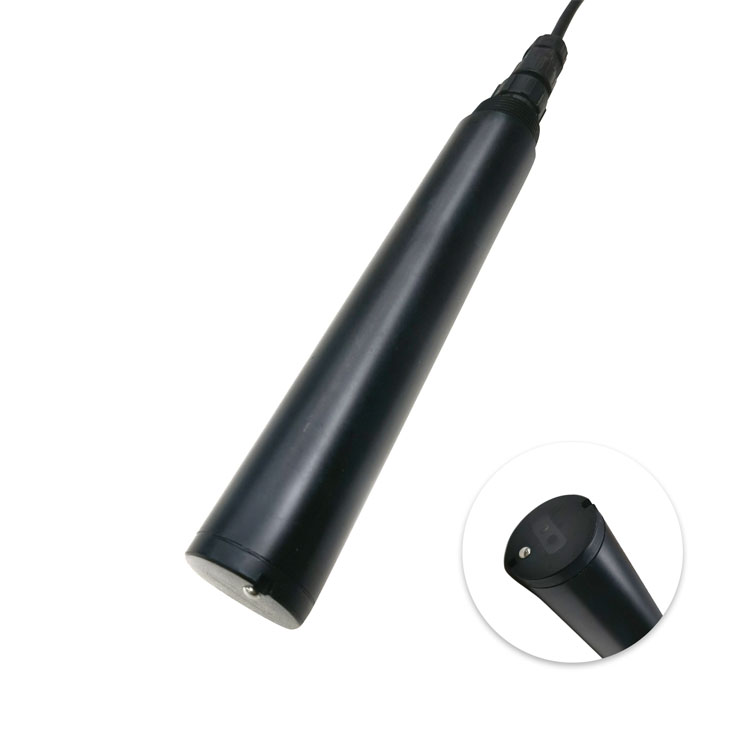
The BOD-related optical probe below needs its own measurement interpretation. A shared PLC connection does not make its registers, calibration commands or failure values interchangeable with those of the pH probe.

| Symptom | Useful investigation | Action not justified by that symptom alone |
|---|---|---|
| No valid reply | Supply, interface, polarity, address and serial settings | Electrode recalibration |
| Communication exception | Supported function, register start and requested count | Assuming the returned exception code is a water measurement |
| Repeatable decimal error | Register pairing, decimal count and engineering conversion | Changing the probe slope to compensate for host scaling |
| Plausible but frozen value | Last successful read, timestamp and retained-value behaviour | Calling the electrode stable without checking fresh data |
| Direct and host values agree but the process result is suspect | Sampling, mounting, temperature and electrode verification | Blaming the serial link after the conversion has been established |
A turbidity probe may continue updating while the pH channel has failed. Retain separate quality states rather than using one controller-online flag for every value. The availability of a neighbouring instrument does not demonstrate a valid pH acquisition.
Store the time of the last successful pH read. On a failed request, keep the error condition separate from the measured value. Do not replace missing data with zero: pH zero has a physical meaning and is not a universal communications-failure code. Do not assume an undocumented number, such as the largest register value, is a specified fault indication.
If the host retains the last good value for display, label it as stale when the freshness requirement is exceeded. Select that requirement for the process and actual polling behaviour. A network dashboard showing a recent upload time can still contain an old pH acquisition, so retain the two times separately where relevant.
Where pH enters a dosing calculation, the control engineer must define the response to unavailable or questionable data. Checking Modbus conversion is not validation of the whole dosing loop. Test the required control behaviour independently with the responsible engineering team.
After establishing the conversion, disconnect the communications path in a controlled test and verify the unavailable indication. Restore it and confirm that a fresh reading is accepted with the correct time. Repeat a controlled restart if it is part of the commissioning procedure. Check that the host does not silently restore an old cached value as a new measurement.
Keep a small accepted record containing device identity, serial settings, register convention, returned example and decoded values. Include it when replacing a probe or controller so the next technician does not reconstruct the format from an unrelated channel.
A separate ammonium measurement can depend on additional water-condition information for its intended interpretation. Identify any use of the pH channel in derived results. If pH is unavailable, a dependent result should not appear fully valid merely because the ammonium device still communicates.
Not for the described NBL-WQ-PH layout. It uses four 16-bit integers arranged as value and decimal-count pairs. Confirm the delivered model and firmware before applying that definition to another device.
Check the returned decimal-count word and any additional scaling already applied by the PLC or display. Double conversion or a copied fixed divisor can create that error. Compare raw words before changing calibration.
No. The device address identifies the responding instrument. Function 03 identifies a holding-register read operation. They are separate fields even when both happen to contain the number three in an example transaction.
No. It establishes a data-conversion result under the tested condition. Electrode condition, installation and calibration need their own checks. Conversely, an electrode adjustment cannot repair a wrong host register definition.
Provide the delivered model, controller details, wiring definition, serial settings, requested register range and raw request/response data. Add the decoded and displayed pH and temperature, timestamps and recent configuration changes. NiuBoL can then locate the problem without assuming an electrode failure.
Not directly. The described probe has a digital serial output, whereas an analogue electrode or transmitter input expects a different electrical signal. Use a supported RS485 acquisition path or assess a separately specified compatible instrument; do not connect A/B to a millivolt input.
Only after checking the delivered model, interface, firmware definition and configuration. Compare a direct read with the host again, including both pH and temperature. A familiar product-family name does not prove that the old address or conversion remains correct.
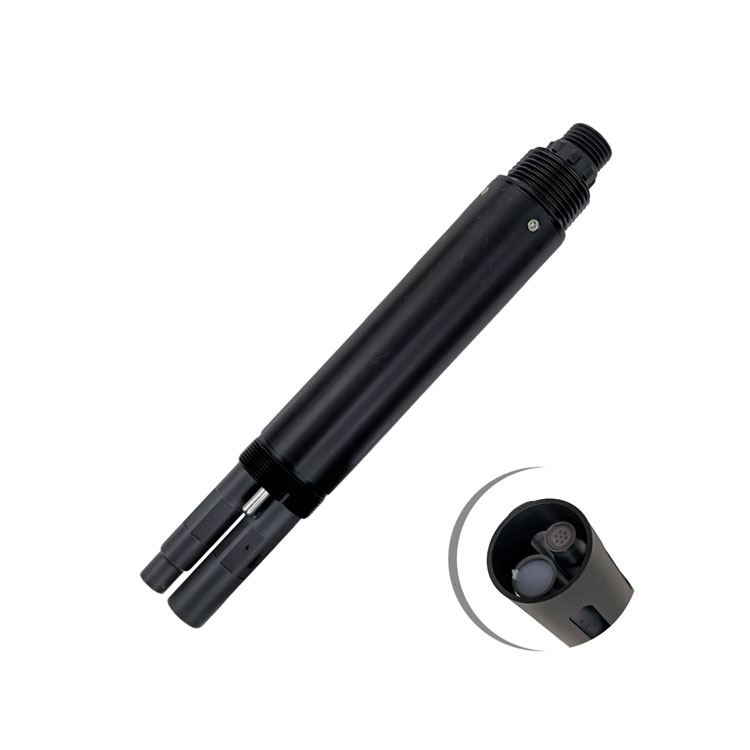
A digital pH water quality tester needs a correctly interpreted and time-valid data path. For NBL-WQ-PH, confirm the four-register integer-and-decimal layout and distinguish device address from function code. Prove the read, conversion and recovery behaviour before altering calibration or using the channel in process control.
Prev:TDS Conductivity Sensor: Prevent Double Conversion in a Gateway
Next:Instrument to Measure Dissolved Oxygen in Water: Test Response Lag
Related recommendations
Sensors & Weather Stations Catalog
 Agriculture Sensors and Weather Stations Catalog-NiuBoL.pdf
Weather Stations Catalog-NiuBoL.pdf
Agriculture Sensors Catalog-NiuBoL.pdf
Water Quality Sensor Catalog-NiuBoL.pdf
Related products
 Combined air temperature and relative humidity sensor
 TDR Soil Moisture & Temperature Sensor for irrigation| RS485 |4-20mA| NBL-S-THR
 Soil pH sensor RS485 soil Testing instrument soil ph meter for agriculture |NBL-S-PH
 Wind Speed sensor Output Modbus/RS485/Analog/0-5V/4-20mA
 Tipping bucket rain gauge for weather monitoring auto rainfall sensor RS485/Outdoor/stainless steel
 Pyranometer Solar Radiation Sensor 4-20mA/RS485


Screenshot, WhatsApp to identify the QR code
WhatsApp number:+8615367865107
(Click on WhatsApp to copy and add friends)

