







How do you know a water quality flow cell is measuring the new sample rather than the previous one? A timer alone cannot answer. Confirm that representative water reaches the sensing surfaces, then assess each required channel against an agreed stability test. Three exchanged volumes give about 95% new water only in an ideal, completely mixed volume; that is a model result, not an acceptance rule for every tube, cell or probe.
Separate sample arrival, exchange and sensor response
Arrival is the transport of changed water from the takeoff to the cell. Exchange describes how old water leaves the cell and its connected spaces. Sensor response describes how each measuring element follows the water actually touching it. Temperature equilibration, transmitter filtering and the receiving system can add further delay.
Those processes can overlap. It is generally wrong to add a calculated three-volume flush to one datasheet T90 and call the sum a guaranteed stable-reading time. T90 describes reaching 90% of a defined response change under specified test conditions; it is not complete settling or proof that a particular acceptance tolerance has been met.
A fast channel may become usable before a slower one. If the project needs one accepted multiparameter record for a sample, accept it only when all required channels qualify. Preserve individual channel times and status where asynchronous records are permitted. Do not silently assemble a single record from different samples.
Map the installed water path before setting a timer
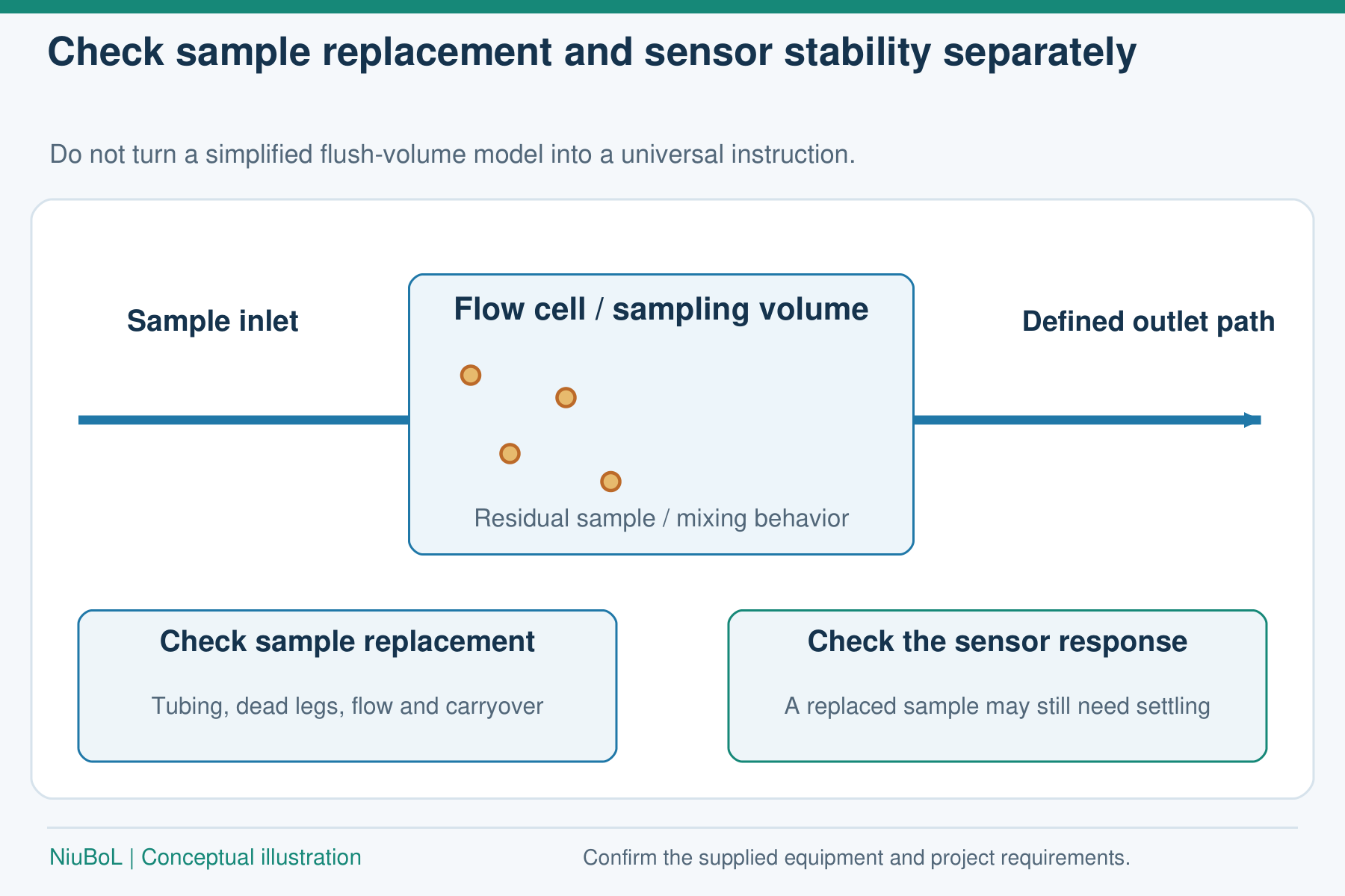
Conceptual sampling path, not an installation drawing. Check tubing, internal geometry, flow and sensor response; a fixed number of flush volumes does not validate every arrangement.
Include the supply tube, selector valve, fittings, cell and any connected branches. Distinguish a flowing transport volume from a stagnant recess: both contain water, but a blind pocket may exchange only slowly. Shorten unnecessary lines and eliminate avoidable dead legs rather than compensating indefinitely with more flushing.
Measure flow at the installed cell under its actual operating restriction. A pump nameplate does not establish delivered sample flow. Recheck after changing tubing or cleaning a restriction. Keep the cell shaded where heating can alter the sample, and arrange the inlet, outlet and probe positions to avoid trapped gas and stagnant sensing regions.
An airtight, continuously renewed path matters particularly for dissolved oxygen and other measurements affected by contact with air. A visible stream at the drain is not enough if a sensing tip remains in an air pocket. Follow each probe's orientation, immersion and clearance requirements when assessing a proposed shared assembly.
What the three-volume calculation really says
Here is one illustrative calculation based on assumed site values, not a measured field record. Assume a 0.250 L cell behaves as one completely mixed volume, supplied continuously at 0.500 L/min. Let the inlet switch abruptly from an old conservative tracer concentration to a new constant concentration at the cell inlet, with no reaction, adsorption or stagnant pockets.
For this ideal cell, the normalized difference from the new concentration is r = exp(−Qt/V). After three turnovers, r = exp(−3) = 0.0498: approximately 5% of the original concentration difference remains. The corresponding time is 3V/Q = 3 × 0.250 / 0.500 = 1.50 minutes, or 90 seconds.
The result starts when the changed inlet reaches this ideal cell; it excludes upstream transport and probe dynamics. A near plug-flow path instead displaces water with a moving front, while real tubing can have dispersion and a long tail. Do not model the whole installed line-plus-cell as a single stirred tank without evidence. Nor should pH be averaged as though it were a conservative concentration: acid-base reactions and buffering affect a mixture's pH.
The practical question is whether remaining carryover matters to the next decision. A small residual from a much stronger preceding sample can still bias a dilute sample substantially. Validate that transition instead of automatically adding one more turnover.
Prove renewal with an installed transition test
Before automatic use, make a controlled switch between compatible waters with a distinguishable, suitable measurement signal. Where conductivity is used, keep the change inside the selected range, control or record temperature, and remember that sensor response forms part of the observed transition. Follow the site's handling and disposal procedure; do not inject an arbitrary tracer into production water.
Record the selector change, measured flow and channel histories through to the accepted endpoint. Test both directions where carryover matters, including a high-to-low transition and the slowest permitted sample flow. Repeat after changes to the cell or tubing. An extended tail suggests that additional waiting or a redesigned path needs investigation; the test alone does not identify its cause.
For switched points, retain sample identity throughout flushing and acceptance. Mark transitional readings as unavailable for the next sample's final result. If sample order can be changed, consider low-to-high sequences, but verify the eventual high-to-low return as well. Scheduling does not remove the need for a carryover test.
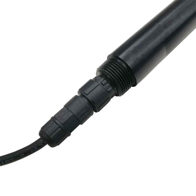
A liquid conductivity channel can observe a suitable transition; the probe image is not a validated flow-cell design.
Define stability without mistaking a flat line for fresh water
Write a channel-specific test before acceptance. Define the observation interval, window length, allowable spread or slope, required consecutive passing windows and maximum wait. Choose these from the measurement objective, actual sensor performance and process variability, then demonstrate them during commissioning. Display resolution alone is not a justified tolerance.
| Acceptance question | Evidence to retain | Failure response |
|---|---|---|
| Has the selected water reached the sensing region? | Installed renewal test and current flow status | Mark the sample transitional or invalid |
| Has each required channel stabilized? | Time-stamped readings and its agreed test | Continue observation within the approved limit |
| Is the temperature basis consistent? | Temperature and compensation settings | Resolve the mismatch before comparison |
| Is the value genuinely fresh? | Measurement age, sample identity and device status | Flag stale or failed data |
A stopped-flow cell, a frozen register or a heavily filtered transmitter can produce a flat trace. Stability therefore needs valid flow and fresh observations as well as a small change. Define a timeout and fault response for the actual application; a universal 600-second cutoff is no more defensible than a universal three-volume rule.
USGS field guidance treats representative sampling, sensor equilibration and sequential stability checks as separate concerns. Its groundwater procedures are not a ready-made recipe for an industrial sample selector. Use the project's applicable method and data-quality requirements rather than borrowing a well-purging rule for a small flow cell.
Match the probes without merging their operating limits
The NBL-WQ-PH pH sensor has a listed range of 0–14 pH, resolution of 0.01 pH and accuracy of ±0.1 pH. Its operating pressure is below 0.2 MPa. These specifications do not establish a stable-reading window or compatibility with every concentrated chemical.
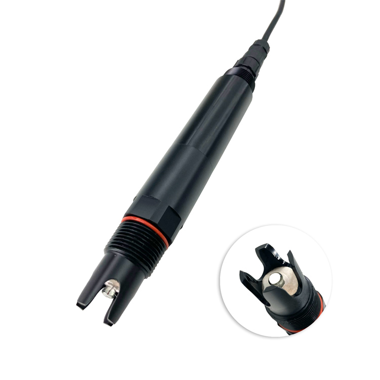
Confirm orientation, wetting and service access for the actual holder rather than selecting it by thread size alone.
The NBL-WQ-EC conductivity sensor has several range options and RS485 Modbus RTU output. Its current page lists a pressure limit below 0.6 MPa; that does not raise the pH probe's limit or approve the cell, seals and fittings. Check every component and applicable transient condition independently.
For acquisition, verify the delivered register map, decimal scaling, units, temperature-compensation basis and measurement age. NiuBoL's sensor listings establish available measurement components, not a complete sample-switching panel. Specify the selector, hydraulics and acceptance logic with the responsible system integrator.
Questions about flow-cell sample acceptance
Q1. Is three volumes enough to accept a new sample?
Not as a universal rule. It gives about 95% exchange only under the stated completely mixed model. Validate installed renewal, important carryover transitions and the required channels' stability before accepting the result.
Q2. Can I add T90 to the flush time?
That can be a provisional planning allowance, but it is not a validated endpoint. Transport, exchange and probe response can overlap, and 90% response may not meet the permitted residual error. Test the complete installed transition.
Q3. Does a stable pH reading prove the cell has fresh water?
No. Old water can remain stable, and a stopped-flow or stale-data fault can appear flat. Confirm renewal and fresh sensor observations alongside the channel's stability test. Do not calculate mixed-water pH by linear interpolation.
Q4. Should every channel wait for the slowest probe?
For a single accepted multiparameter record, all required channels must qualify. Separate records can use individual acceptance times if the project permits it and retains sample identity, timestamps and validity explicitly.
Q5. What should follow a high-concentration sample?
Apply a validated cleaning or renewal procedure compatible with the probes and liquids, then verify the high-to-low transition. An extra fixed volume is not proof that residues or slow-exchanging pockets no longer affect the next result.
Q6. How can the maximum sampling rate be specified?
Measure accepted cycle time across the necessary sample transitions, including switching, renewal, stabilization and fault handling. Do not promise samples per hour from nominal pump flow and a datasheet response time alone.
Accept a demonstrated sample, not an elapsed timer
A defensible flow-cell record connects sample identity, proven renewal, fresh observations and channel-specific stability. Use volume and flow to plan the test, then validate the installed response under the important transitions. Keep failures visible rather than allowing a quiet trace or a completed timer to authorize an unrepresentative result.
Ask NiuBoL about sensor fit using the water type and measurement goal, the existing probe or receiver model, and a sample-path sketch. These details support pH or conductivity sensor selection, acquisition-interface checks and a quotation for suitable monitoring components.









