





— Blogs —
—Products—
 Consumer hotline +8618073152920
WhatsApp:+8615367865107
Address:Room 102, District D, Houhu Industrial Park, Yuelu District, Changsha City, Hunan Province, China
Product knowledge
Time:2026-08-21 09:06:00 Popularity:294
A TDS conductivity sensor can produce a stable EC reading while a new gateway displays a different TDS value. Before recalibrating the probe, find where the EC-to-TDS conversion occurs. The sensor, PLC and cloud platform must not each apply a coefficient to a value that has already been converted.
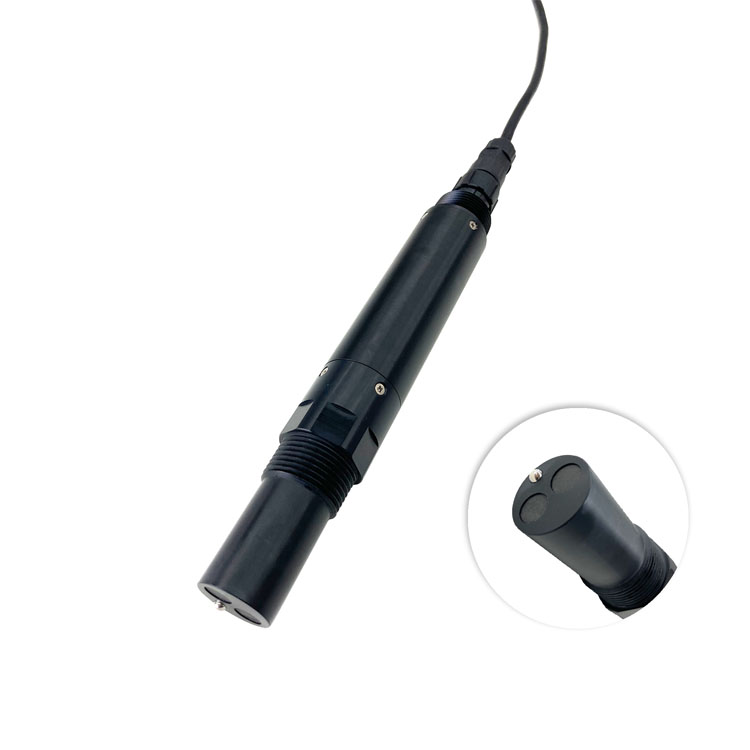
The NiuBoL NBL-WQ-EC provides conductivity, temperature and calculated TDS where supported by the selected range. Conductivity is the electrical measurement; TDS is derived using a conversion coefficient. A value already labelled and decoded as TDS must not be passed through an EC conversion function again.
For an illustrative calculation, 500 uS/cm multiplied by a factor of 0.64 gives 320 mg/L. If software mistakenly treats that 320 as EC and multiplies it again, the displayed result becomes 204.8 mg/L. Those are arithmetic examples, not measured water results or proof that 0.64 describes every water composition.
| Acquisition path | Correct handling | Common error |
|---|---|---|
| Read the probe's TDS field | Decode its value, decimal position and unit once | Apply an additional EC-to-TDS factor in the gateway |
| Read EC and calculate TDS in the host | Use one identified coefficient and temperature basis | Change the coefficient during migration without recording the change |
| Read EC in mS/cm | Convert to the unit expected by the chosen calculation | Use the number as uS/cm, producing a factor-of-1000 error |
| Export both EC and TDS | Label the measured and derived fields distinctly | Rename the same field or compare unlike units as if they were equivalent |
A separate pH probe should keep its own channel definition. Reusing a generic water-quality transformation for every incoming number can apply an EC coefficient to a pH value. Check parameter identity before checking whether a number falls within a plausible range.
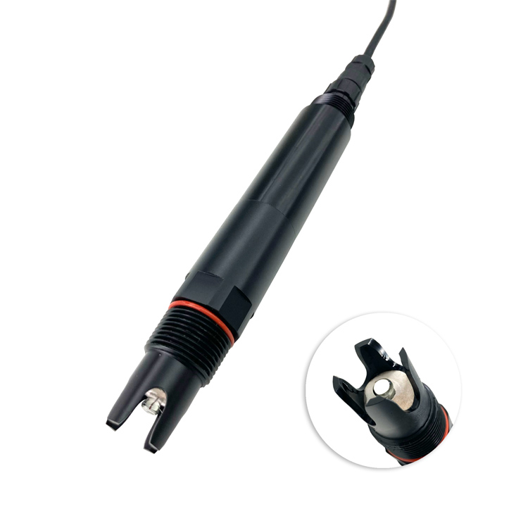
The NBL-WQ-EC measurement block begins at 0x0000 and includes six 16-bit registers: conductivity value, EC decimal position, temperature value, temperature decimal position, TDS value and TDS decimal position. Use the protocol for the delivered configuration; range selection affects scaling.
Keep raw reply examples and the decoded engineering values when commissioning. A gateway template from another span can produce a neat but wrongly scaled number. Device address and baud rate compatibility do not establish correct units, parameter selection or conversion.
| Specification | NBL-WQ-EC value | Migration check |
|---|---|---|
| Selected EC range | 0-20.00 uS/cm; 0-200.0 uS/cm; 0-5000 uS/cm; or 0-200.0 mS/cm | Preserve the actual range, unit and decimal handling |
| Accuracy | +/-1% FS; temperature +/-0.3 degrees C | Software agreement cannot improve the probe's measurement limit |
| TDS coefficient | Configurable; default 0.64 | Read the installed setting rather than assuming the default remains unchanged |
| Compensation | Pt1000 automatic temperature compensation | Confirm which compensated EC field and reference conditions feed the calculation |
| Supply and power | 12-24 V DC +/-10%; 0.2 W at 12 V | Check actual probe supply after panel or gateway changes |
| Interface | RS485 Modbus RTU; default 9600 bps, N, 8, 1 | Use the delivered address and communication settings |
| Water and construction limits | 0-50 degrees C; pressure below 0.6 MPa; IP68; 5 m standard cable, customizable | Retain the correct process installation and external cable protection |
Wetted-material options include ABS, SUS316L and PVC depending on configuration. A software migration does not extend chemical compatibility or process limits. If the work also changes the water connection, review those conditions independently.
A turbidity instrument measures optical scattering, not the dissolved ionic content used for EC conversion. Agreement or disagreement on that channel cannot establish which TDS coefficient the gateway should use.
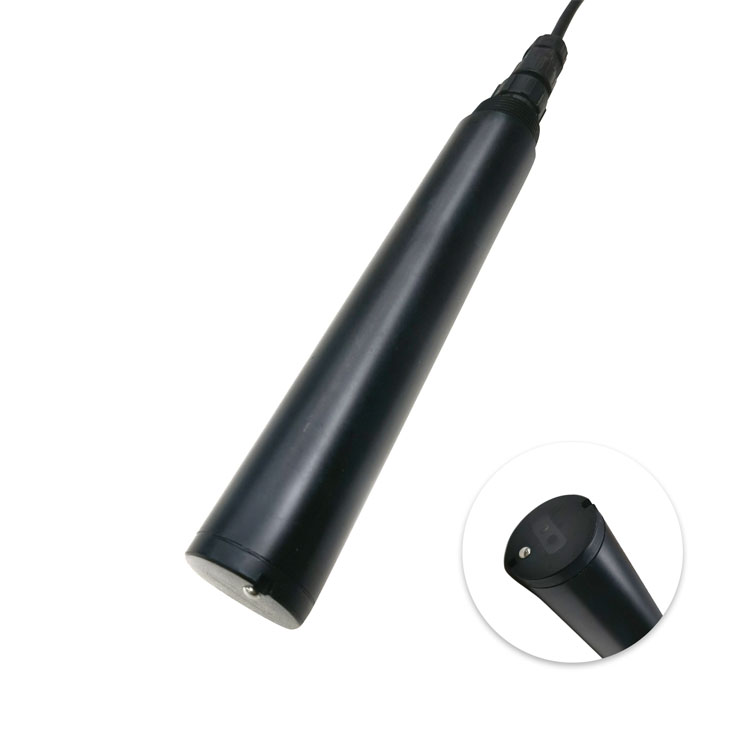
Use suitable reference checks when the underlying EC measurement is in doubt. Do not recalibrate a sound conductivity probe merely to make a misconfigured cloud number agree with the former display. Correct the acquisition or calculation layer where the discrepancy originates.
A second pH assembly may use a different register layout and compensation element from the base pH model. Maintain model-specific mappings for companion channels during the same gateway change; do not clone the EC decoding across them.
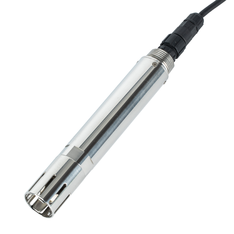
Choose one defined calculation path. Either use the correctly decoded native TDS field or derive TDS once from EC with an identified coefficient. Do not apply both conversions to the same value.
No. It is the configurable default for this EC family, not a universal chemical relationship. Validate the conversion for the actual water and required interpretation.
Investigate field selection, decimal scaling, units and conversion coefficients. It does not by itself establish a probe calibration fault.
Do not add competing masters to the same bus. Use an approved acquisition arrangement with one active master or another controlled method that preserves valid source observations.
Preserve the original values and calculation basis. If a separately identified recalculated series is needed, retain its method and change history so it is not mistaken for the original observation.
No. Salinity and EC-derived TDS have different interpretation and conversion requirements. Evaluate a suitable salinity configuration when salinity is the required parameter rather than renaming a TDS tag.
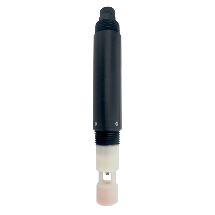
A TDS conductivity sensor migration should preserve the meaning of each value, not just restore communication. Identify the conversion owner, retain correct units and decimals, and compare source EC before changing calibration. NiuBoL can review the probe range and interface when the old and new gateway mappings and water conditions are available.
Prev:Turbidity Measuring Device: Cleaning Without Losing the Baseline
Next:Digital pH Water Quality Tester: Fix PLC Scaling and Stale Data
Related recommendations
Sensors & Weather Stations Catalog
 Agriculture Sensors and Weather Stations Catalog-NiuBoL.pdf
Weather Stations Catalog-NiuBoL.pdf
Agriculture Sensors Catalog-NiuBoL.pdf
Water Quality Sensor Catalog-NiuBoL.pdf
Related products
 Combined air temperature and relative humidity sensor
 TDR Soil Moisture & Temperature Sensor for irrigation| RS485 |4-20mA| NBL-S-THR
 Soil pH sensor RS485 soil Testing instrument soil ph meter for agriculture |NBL-S-PH
 Wind Speed sensor Output Modbus/RS485/Analog/0-5V/4-20mA
 Tipping bucket rain gauge for weather monitoring auto rainfall sensor RS485/Outdoor/stainless steel
 Pyranometer Solar Radiation Sensor 4-20mA/RS485


Screenshot, WhatsApp to identify the QR code
WhatsApp number:+8615367865107
(Click on WhatsApp to copy and add friends)

