





— Blogs —
—Products—
 Consumer hotline +8618073152920
WhatsApp:+8615367865107
Address:Room 102, District D, Houhu Industrial Park, Yuelu District, Changsha City, Hunan Province, China
Product knowledge
Time:2026-02-20 11:45:17 Popularity:703
Quick Answer: Doppler flow monitoring for urban sewer networks combines submerged velocity measurements, water depth and pipe geometry to estimate discharge. Its value is in interpreting changes across dry weather, rainfall, backwater and possible reversal. A flow probe does not identify pollutants, guarantee overflow prevention or make a manhole installation safe without a separate site assessment.
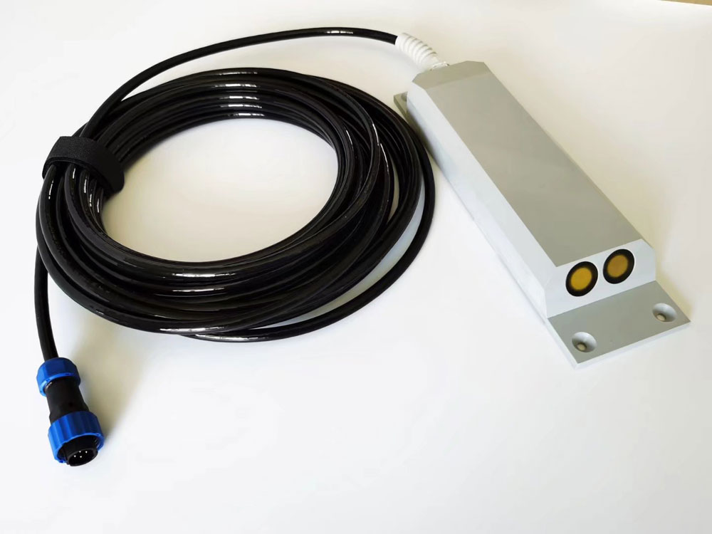
A sewer survey may investigate wet-weather inflow, compare subcatchments, check pumping behavior or observe conditions near an overflow. These tasks need different measuring points. A convenient access chamber may contain turbulent junction flow that is unsuitable for a representative velocity measurement.
For each point, identify upstream branches, downstream controls and the pipe section to which the calculated flow applies. Note whether pumping, tide or downstream surcharge can alter the direction. These conditions matter more than assigning every manhole the same sensor and reporting interval.
The probe transmits acoustic energy through the water and evaluates scattering from moving particles or small bubbles. A pressure channel measures depth at its reference, and the system combines depth and velocity with the configured section. The sensor is in contact with sewage and needs appropriate installation and servicing.
The measured acoustic velocity is not necessarily the section's mean velocity. Junctions, bends, drops, deposits and swirling flow can alter that relationship. Establish the measuring reach and validate its discharge response; a factory velocity specification does not establish the complete site's flow uncertainty.
Acoustic scattering is necessary, but excessive bubbles, attenuation or a covered sensing face can still impair the result. A usable sewage flow meter installation needs a way to distinguish valid readings from poor returns and sensor exposure. Do not convert every invalid reading to zero flow.
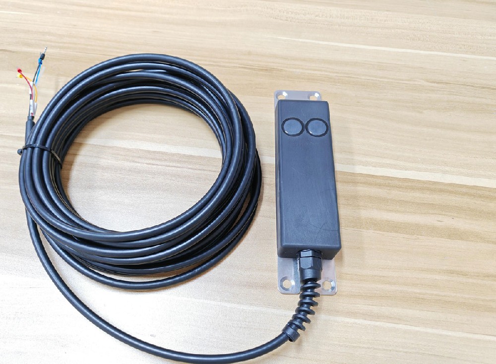
The NiuBoL Doppler velocity meter family includes different configurations. A forward-flow canal probe is not automatically a suitable substitute where a sewer reverses. The following bidirectional option illustrates the limits that need to be checked against the proposed survey.
| Bidirectional option | Specification and survey implication |
|---|---|
| Velocity magnitude range | 0.03-10 m/s, with direction identification; verify how direction and net totals are encoded |
| Velocity accuracy | +/-1.0% +/-1 cm/s specified over 0.03-5 m/s; do not extend that accuracy statement to 10 m/s without confirmation |
| Water depth | 0.03-5 m; accuracy notation 0.3% +/-0.5 cm, with percentage basis to be confirmed |
| Temperature | -10 to 60 degrees C; stated measurement accuracy +/-1 degree C |
| Supply | 10-30 VDC for this option |
| Current at 12 V | 72 mA standby; 126 mA while measuring |
| Measurement interval | Configurable; default 3 seconds, minimum 2 seconds for this option |
| Communication | RS485 / Modbus RTU |
| Protection and housing | IP68; ABS housing for this option, not an explosion-protection certification |
| Cable and reference | Preserve the required pressure-reference arrangement; specify cable length, jacket compatibility and protected termination |
The ordinary unidirectional configuration has a different velocity span and electrical consumption. Select by model and revision, not housing resemblance. Likewise, a 0.03 m depth span limit does not establish the minimum cover needed for valid acoustic velocity measurement.
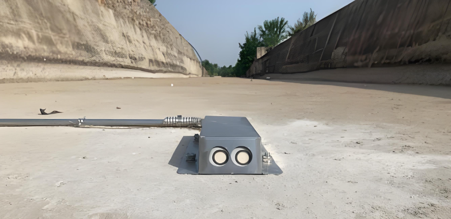
For a partially filled circular pipe, wetted area changes nonlinearly with depth. Use the surveyed internal diameter, actual invert and relevant deposits. A sensor raised on a plate measures pressure above its own reference; the configured section needs the corresponding elevation offset.
Illustrative example: a clean 0.6 m diameter pipe flowing exactly half full has about 0.1414 m2 of wetted area. With a validated mean velocity of 0.7 m/s, discharge is approximately 0.099 m3/s, or 356 m3/h. The calculation assumes that the velocity represents the section; it is not a project result.
If deposits occupy part of that nominal area, using the clean-pipe geometry overstates water area. Deposits also alter the velocity field, so subtracting a rough sediment estimate alone is not a complete correction. Reinspect and update the section when cleaning, construction or deposition changes it.
When a pipe surcharges, depth above the crown no longer increases the pipe's internal cross-sectional area. Pressure and acoustic limits, the full-pipe calculation mode and the installation must all be suitable. A sensor described for non-full-pipe monitoring should not be assumed valid for every pressurized event.
Compare rainfall timing with depth, velocity and flow at the selected catchment points. A rapid wet-weather rise can guide investigation, but does not uniquely identify illegal connections or a particular defect. Local drainage, travel time, pumping and upstream storage can produce different response patterns.
Increasing depth with decreasing forward velocity suggests a different condition from depth and velocity increasing together. Review downstream level and pump status before concluding that a blockage is present. The monitoring system should support investigation, not label one signal pattern as a proven fault.
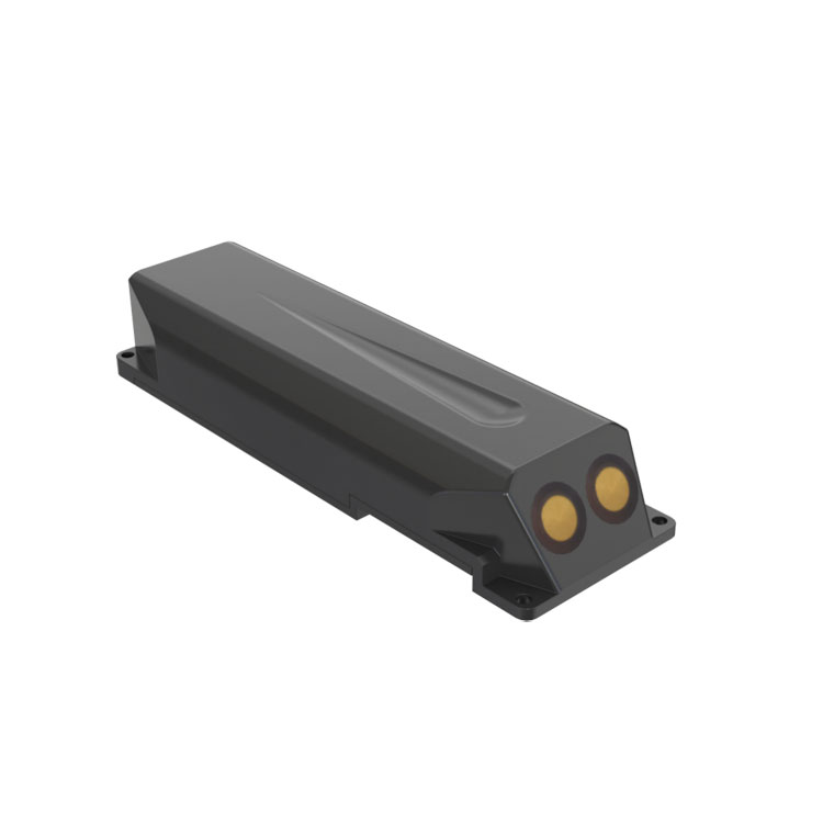
If the site can reverse, retain direction as well as magnitude. An event with 100 m3 forward and 30 m3 reverse has a net forward volume of 70 m3. Adding absolute movement gives 130 m3, which is useful for a different purpose but is not net conveyance.
Confirm whether the instrument provides separate forward, reverse and net counters, and how the logger handles their resets. A reverse-direction flag should not be discarded by a dashboard that displays only positive magnitudes.
Comparing two sensors is not simply subtracting simultaneous readings. Water takes time to travel, intermediate branches contribute flow, and a rising water level can store volume between the points. Check time synchronization and the relevant network layout before interpreting a difference.
For example, an upstream 0.08 m3/s and downstream 0.11 m3/s differ by 0.03 m3/s, equivalent to 108 m3/h if sustained. That number alone does not prove infiltration, a leak or instrument error. Establish the time relation, intervening inputs and uncertainty before allocating a cause.
A flow observation is also not a water-quality test. Identifying a contaminant requires the appropriate analysis or sensor, with its own location and timing. Multiplying an unrelated concentration sample by a peak flow cannot establish the event's pollutant load.
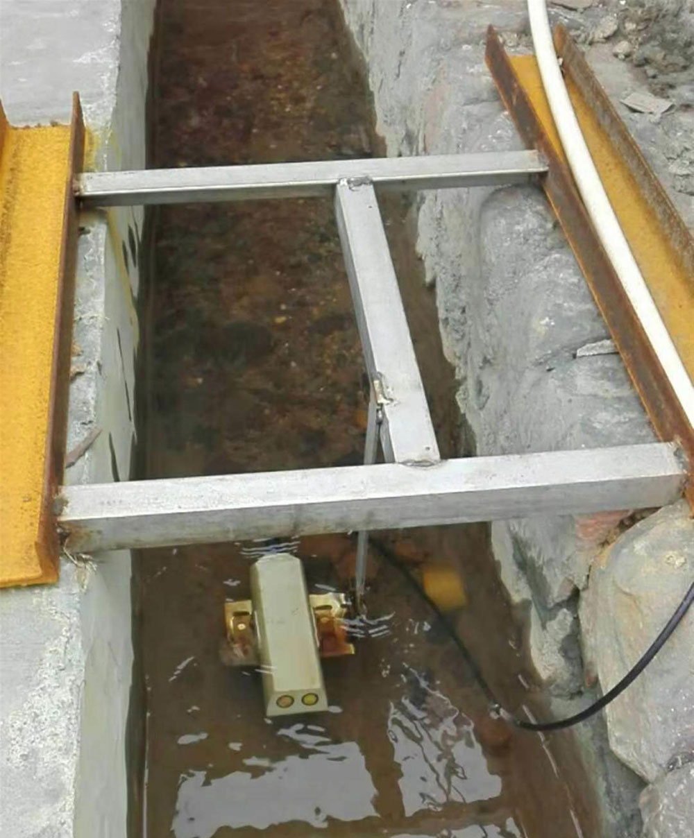
The submerged probe connects to an RTU or data logger by RS485 / Modbus RTU. Cellular or other remote transport is a separate part of the installation. A sound serial connection does not establish adequate radio coverage through a metal cover or a deep chamber.
Test the final antenna arrangement, approved cable route and coverage at the actual site. Keep electronics, joints and pressure-reference terminations suitably protected against the relevant flooding conditions. An IP68 probe does not make a modem, connector or cabinet safe to submerge.
Use measurement intervals that capture the event, while selecting upload frequency around the reporting need and available energy. At 12 V and 126 mA, continuous measurement is approximately 1.512 W, or 36.3 Wh/day before the logger and communications load. Battery reserve requires the complete operating profile, not a universal solar-panel size.
Choose a section with adequate immersion throughout the intended measuring period and avoid mounting where rags, grit or a drop jet dominate the sensing zone. Secure the assembly against movement and protect the cable from debris loads. Raising a probe to avoid burial changes its position and may change the velocity relationship.
Manholes and sewers can present hazardous atmospheres, sudden inflow and other confined-space risks. Arrange access and servicing through qualified personnel under the applicable site procedures. IP68 is not evidence of suitability for an explosive atmosphere, and this flow-monitoring description is not an entry procedure.
For maintenance, record the as-found depth, velocity, deposits and clock status before cleaning or adjustment. Recheck after service at comparable conditions. Do not assume a fixed quarterly visit is adequate where a single storm can move sediment or leave debris over the probe.
At commissioning, compare the depth channel with an independent reference tied to the pipe invert, and confirm the direction indication against an observed operating condition. Review discharge using a suitable independent method at representative flows. Testing only a dry-weather condition does not validate the same geometry and velocity relation during backwater or surcharge.
Save the original observations and configuration alongside any revised flow calculation. If the survey later changes a probe elevation or pipe section, apply the change to the appropriate period rather than silently recalculating the entire history. Distinguish measured intervals from estimates made during a missing-data period. That distinction is particularly important when comparing storm event volumes between monitoring points.

Only when the selected version supports direction identification and the data system preserves it. A unidirectional version should not be assumed to record reversal or net volume correctly.
No. Ingress protection and explosion protection address different hazards. Review the atmosphere classification, electrical suitability, cable termination and safe access separately before installation.
No. Backwater, downstream restrictions, pumps and other network conditions can also raise level. Review velocity direction, rainfall and connected equipment before selecting an investigation or intervention.
Do not assume it. Check pressure exposure, depth span, acoustic conditions and the full-pipe calculation mode for the selected equipment. The nominal pipe area does not keep increasing with pressure head above the crown.
Check travel time, branches, storage, clock agreement, counter resets and each installation's measurement quality. A difference is a reason to investigate, not automatic proof that one instrument is wrong.
Provide pipe dimensions, operating depth and velocity, possible reversal or surcharge, deposits, access restrictions and the survey objective. Include power, antenna and platform arrangements so NiuBoL can distinguish the probe from the complete remote station.
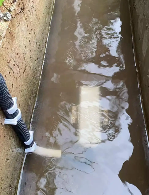
Doppler flow monitoring for urban sewer networks is useful when depth, velocity, direction and pipe geometry are interpreted together. Select the correct configuration, validate the measuring section and keep uncertain events identifiable. Send NiuBoL the network conditions and proposed measuring points for an equipment and integration review.
Prev:Hydropower Ecological Flow Records: Continuous Release Versus Daily Volume
Next:Irrigation Canal Water Balance: Use Radar Flow Records Without Assuming Losses
Related recommendations
Sensors & Weather Stations Catalog
 Agriculture Sensors and Weather Stations Catalog-NiuBoL.pdf
Weather Stations Catalog-NiuBoL.pdf
Agriculture Sensors Catalog-NiuBoL.pdf
Water Quality Sensor Catalog-NiuBoL.pdf
Related products
 Combined air temperature and relative humidity sensor
 TDR Soil Moisture & Temperature Sensor for irrigation| RS485 |4-20mA| NBL-S-THR
 Soil pH sensor RS485 soil Testing instrument soil ph meter for agriculture |NBL-S-PH
 Wind Speed sensor Output Modbus/RS485/Analog/0-5V/4-20mA
 Tipping bucket rain gauge for weather monitoring auto rainfall sensor RS485/Outdoor/stainless steel
 Pyranometer Solar Radiation Sensor 4-20mA/RS485


Screenshot, WhatsApp to identify the QR code
WhatsApp number:+8615367865107
(Click on WhatsApp to copy and add friends)

