





— Blogs —
—Products—
 Consumer hotline +8618073152920
WhatsApp:+8615367865107
Address:Room 102, District D, Houhu Industrial Park, Yuelu District, Changsha City, Hunan Province, China
Product knowledge
Time:2025-11-22 16:30:18 Popularity:1028
Visibility sensor accuracy must be interpreted with the measured quantity, range and verification conditions. The NiuBoL NBL-W-VS estimates Meteorological Optical Range (MOR) using local forward scattering. Its 5 m-10 km span is not a road-coverage distance, and a percentage specification does not describe every error introduced by location, contamination or data processing. Define the required MOR interval and verification method before accepting an instrument for the project.
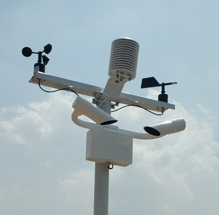
MOR describes atmospheric optical attenuation. It is not a direct measurement of how far an individual driver can see a sign, nor is it automatically Runway Visual Range. The NBL-W-VS detects scattered light in a local sampling volume and converts that response into an optical-range estimate. A large difference between MOR and a person's view does not, by itself, establish an instrument calibration error.
The same distinction matters when comparing instruments. A transmissometer observes attenuation over a defined optical path; a forward-scatter device samples local air. If fog is spatially uneven, nearby instruments can experience different conditions. Record their locations and comparison timing before treating every disagreement as a percentage error of one sensor.
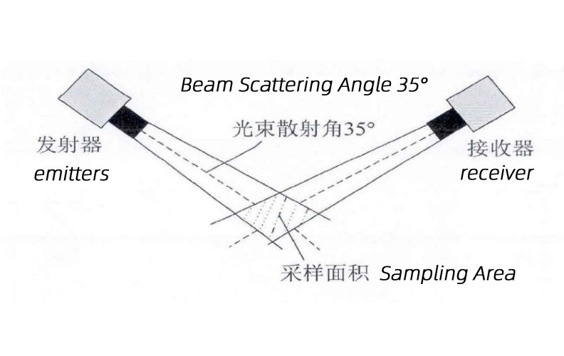
The optical sketch illustrates forward scattering. The NBL-W-VS specification uses a 39-51 degree scattering angle; the 35-degree label in the illustrative sketch is not its model-specific geometry.
| Item | NBL-W-VS specification | Project interpretation |
|---|---|---|
| Measurement | MOR; 5 m-10 km | Output distance, not the length of area monitored |
| Accuracy up to 2 km | 2% | Define tolerance basis and verification conditions for the contract |
| Accuracy from 2 to 10 km | +/-10% | Do not apply the short-range percentage throughout the full span |
| Optical geometry | 39-51 degrees; peak wavelength 875 nm | Model-specific optical characteristics |
| Supply and load | DC 12 V; average 0.8 W | Sensor load, not the total station requirement |
| Interface | RS485 Modbus RTU; default 9600 bps | Verify decoded metres and observation timing |
| Environment | -40 to 80 C; 0-95% RH; IP65 | Review optical exposure and maintenance separately |
The NBL-W-VS visibility sensor has different stated accuracy bands. A project concerned with low-visibility events should identify the interval that matters, not select an instrument only by its maximum range. Clarify whether a contractual percentage refers to the reference value or another defined basis and which test conditions apply.
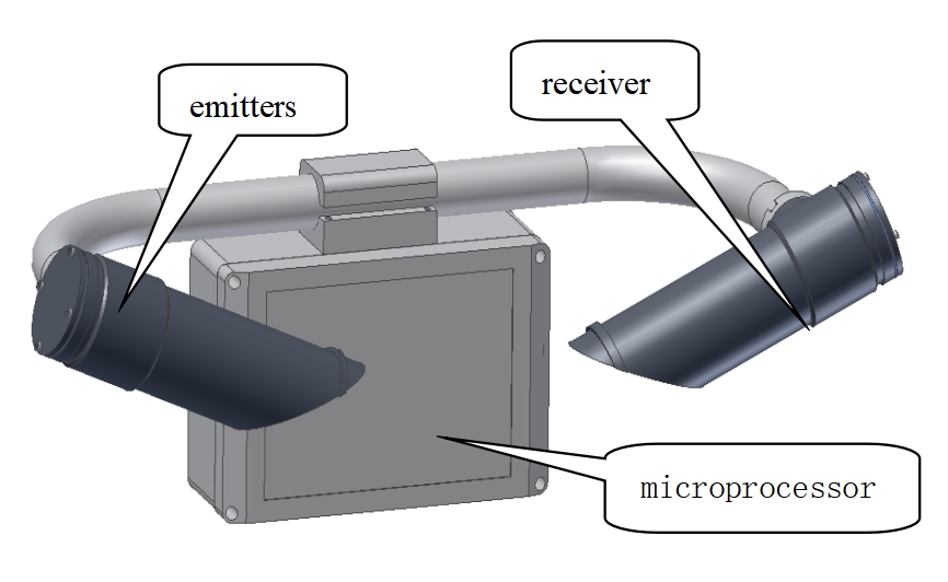
Deposits on optical windows, an obstruction near the sampling area or direct sunlight entering the receiver can affect a field observation. Inspect these conditions before changing a calibration coefficient. Record the as-found condition and readings, then the cleaning or corrective work. Otherwise, a calibration adjustment may hide contamination and leave the cause unresolved.
Use the specified cleaning method and maintain safe access to the optics. A fixed service interval is only a starting point; dust, salt deposits and local exposure can require more frequent inspection. IP65 protection does not mean that external optical surfaces remain clean or that every icing condition is covered.
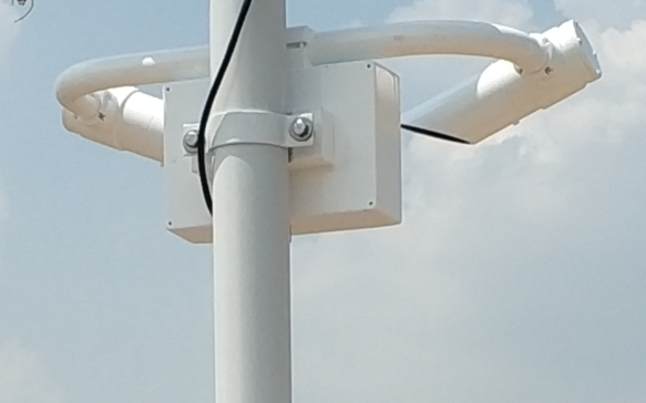
A useful comparison needs an appropriate reference, overlapping measurement conditions and synchronized observations. State the comparison interval, data averaging, reference uncertainty and treatment of unavailable readings. If the reference and test sensor observe different air, describe that limitation rather than reporting their difference as a pure instrument error.
A calibration or verification accessory may check a defined part of the optical response; it does not reproduce every atmospheric particle mixture or prove spatial representativeness. Obtain the procedure applicable to the delivered instrument. Neither visual inspection of a road scene nor an arbitrary software offset is a substitute for that procedure.
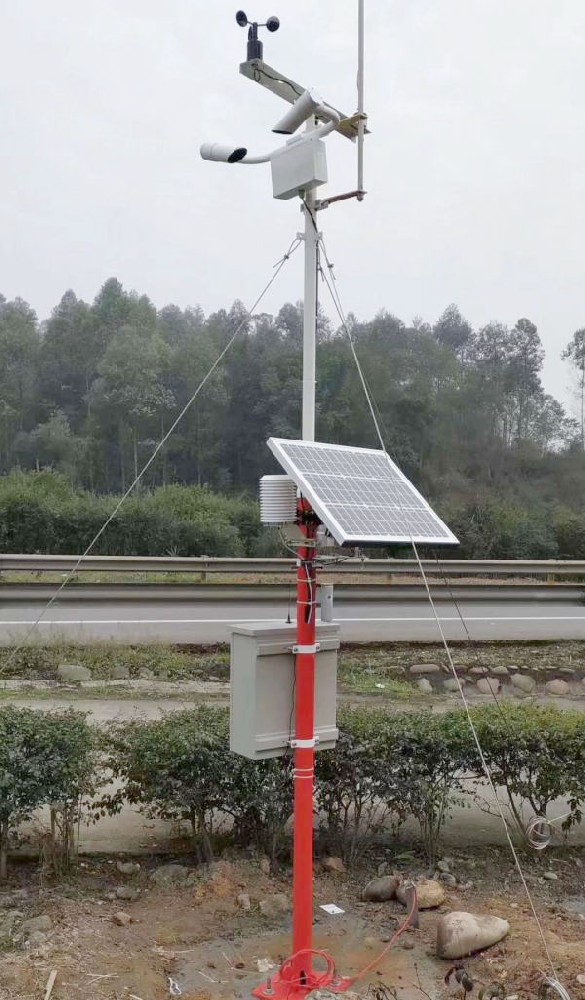
Compare the sensor output with the logger and remote record using the same observation time. A value expressed in metres can be misread as kilometres; a filtered chart can differ from a current reading without a sensor fault. Retrieve the actual records behind the comparison rather than comparing two screens captured at different times.
RS485 Modbus RTU compatibility requires the delivered register map, correct scaling and status handling. Define how out-of-range and unavailable values appear in the receiving system. A displayed upper-limit value does not establish the exact optical range beyond the instrument span, and a missing value must not be interpreted as clear weather.
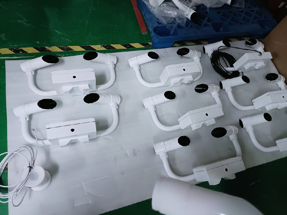
For road and port projects, define which locations and reduced-visibility conditions the observations must represent. Traffic rules, operator decisions and warning delivery need their own requirements. A sensor accuracy specification alone does not demonstrate the performance of the entire response system.
For aviation work, assess MOR, any required RVR system and applicable operational approval separately. Do not infer aviation qualification from a measuring range or an outdoor rating. For a NiuBoL quotation, provide the required interval, site exposure, reference or test method, output destination and documentation requirements so the verification work can be scoped with the instrument.
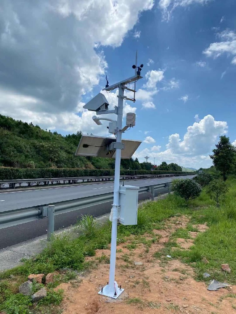
No. The NBL-W-VS specification separates the interval up to 2 km from the 2-10 km interval. Use the applicable band and agreed tolerance basis.
No. It describes the MOR output span. Forward scattering samples local air; monitoring locations follow the conditions the road project needs to observe.
No. Cleaning restores an optical condition; calibration or verification evaluates response using an appropriate procedure. Keep separate records of each activity.
Check location, timing, averaging, optical condition and measurement method as well as calibration. Different air samples or processing periods can create real differences.
No. A project requiring RVR or aviation operational approval must be evaluated separately. An MOR sensor is not a complete approved RVR system by default.
Send the model, required MOR interval, comparison records and times, reference method, optical condition and receiving-system settings. These details distinguish an instrument issue from a site or decoding problem.
NBL-W-VS visibility sensor instructions (PDF)
 NBL-W-VS-Visibility-Sensor-Instruction-Manual.pdf
Visibility sensor accuracy is useful only when its range, quantity and verification conditions match the project. Keep MOR distinct from operational sight distance, inspect optics and compare synchronized records. NiuBoL can review the instrument and test scope once the required monitoring interval and acceptance method are defined.
Related recommendations
Sensors & Weather Stations Catalog
Agriculture Sensors and Weather Stations Catalog-NiuBoL.pdf
Weather Stations Catalog-NiuBoL.pdf
Agriculture Sensors Catalog-NiuBoL.pdf
Water Quality Sensor Catalog-NiuBoL.pdf
Related products
 Combined air temperature and relative humidity sensor
 TDR Soil Moisture & Temperature Sensor for irrigation| RS485 |4-20mA| NBL-S-THR
 Soil pH sensor RS485 soil Testing instrument soil ph meter for agriculture |NBL-S-PH
 Wind Speed sensor Output Modbus/RS485/Analog/0-5V/4-20mA
 Tipping bucket rain gauge for weather monitoring auto rainfall sensor RS485/Outdoor/stainless steel
 Pyranometer Solar Radiation Sensor 4-20mA/RS485


Screenshot, WhatsApp to identify the QR code
WhatsApp number:+8615367865107
(Click on WhatsApp to copy and add friends)

