





— Blogs —
—Products—
 Consumer hotline +8618073152920
WhatsApp:+8615367865107
Address:Room 102, District D, Houhu Industrial Park, Yuelu District, Changsha City, Hunan Province, China
Product knowledge
Time:2025-10-15 15:54:48 Popularity:1607
Ultrasonic water flow meters use acoustic measurements to estimate water velocity, then calculate discharge using the appropriate geometry and measurement model. Transit-time and Doppler methods have different acoustic requirements. A clamp-on pipe meter, an immersed Doppler probe and a radar water-level instrument are not interchangeable, even when all feed the same monitoring platform.
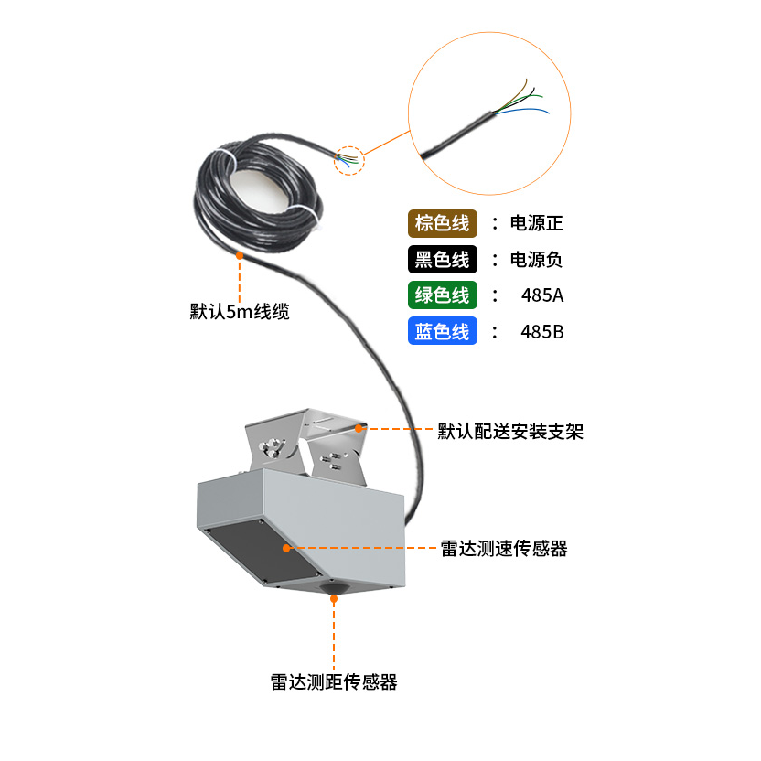
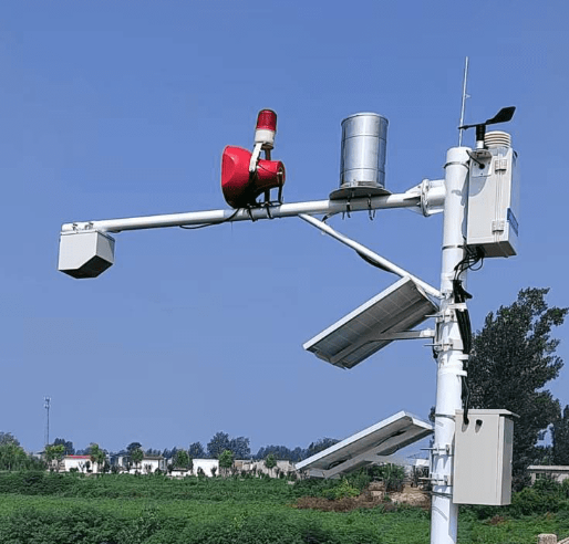
The instrument above is radar surface-velocity equipment, not a clamp-on ultrasonic transducer. It illustrates an alternative hydrological measurement method. The physical quantity and installation method must be identified before comparing a product with an ultrasonic flowmeter.
A transit-time system compares acoustic travel along a path upstream and downstream. Flow changes the two travel times differently. The path geometry and timing are used to calculate velocity. The Bureau of Reclamation Water Measurement Manual describes this principle for acoustic flow measurement.
For an external clamp-on arrangement, sound also passes through the pipe wall and any lining. Pipe dimensions, material, transducer placement and acoustic coupling therefore belong in the configuration. Successful installation on one pipe does not establish suitability for every material or lining.
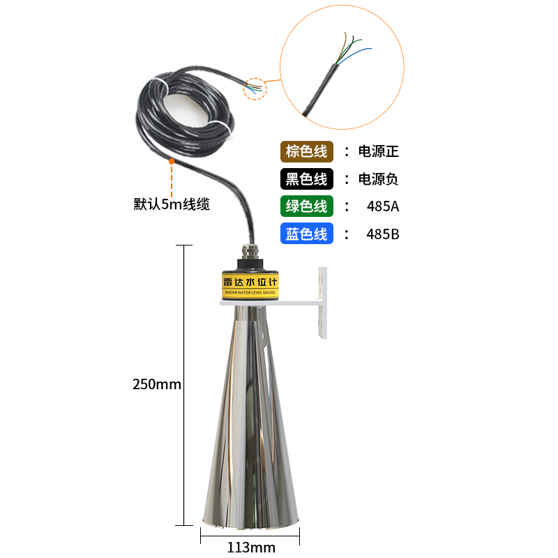
The radar level instrument shown above measures distance to a surface, not acoustic travel through a pipe. Its value can contribute to an open-channel area calculation, but level alone does not provide an independently measured flow rate.
An ultrasonic Doppler instrument uses a frequency shift in sound reflected by material moving with the water. Suspended particles or bubbles can provide reflectors. Their presence does not guarantee a good measurement: concentration, attenuation, velocity distribution and the instrument's position still matter.
Likewise, transit-time suitability should not be reduced to a rigid clean-versus-dirty water rule. The acoustic path must remain usable under the actual conditions. Ask for a site assessment or trial where bubbles, sediment or changing water quality make performance uncertain.
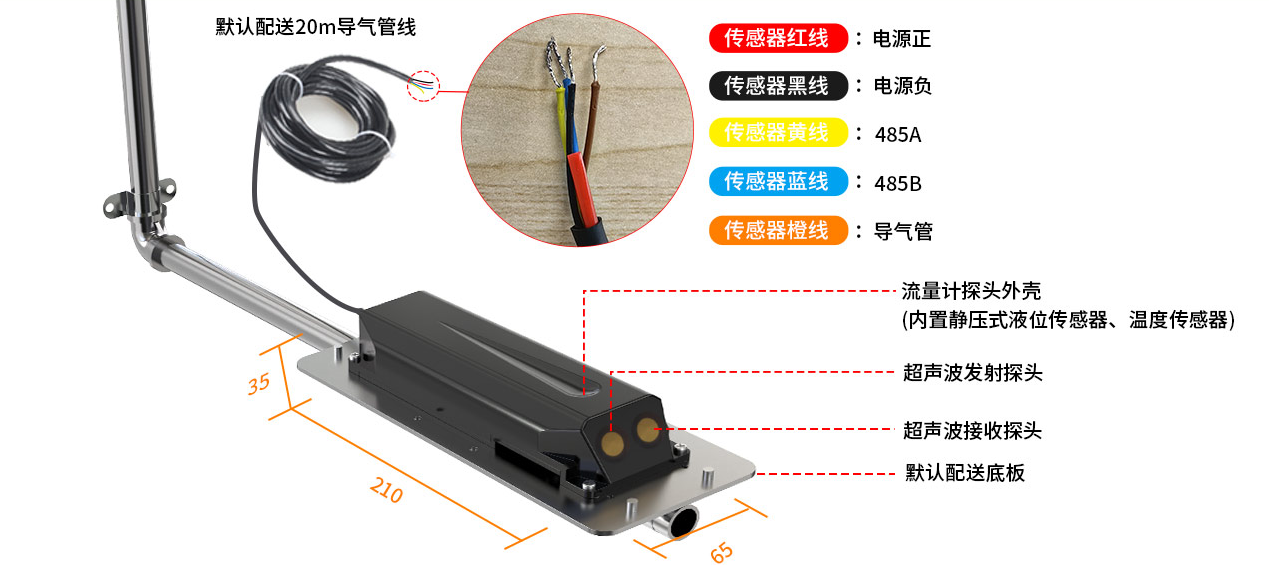
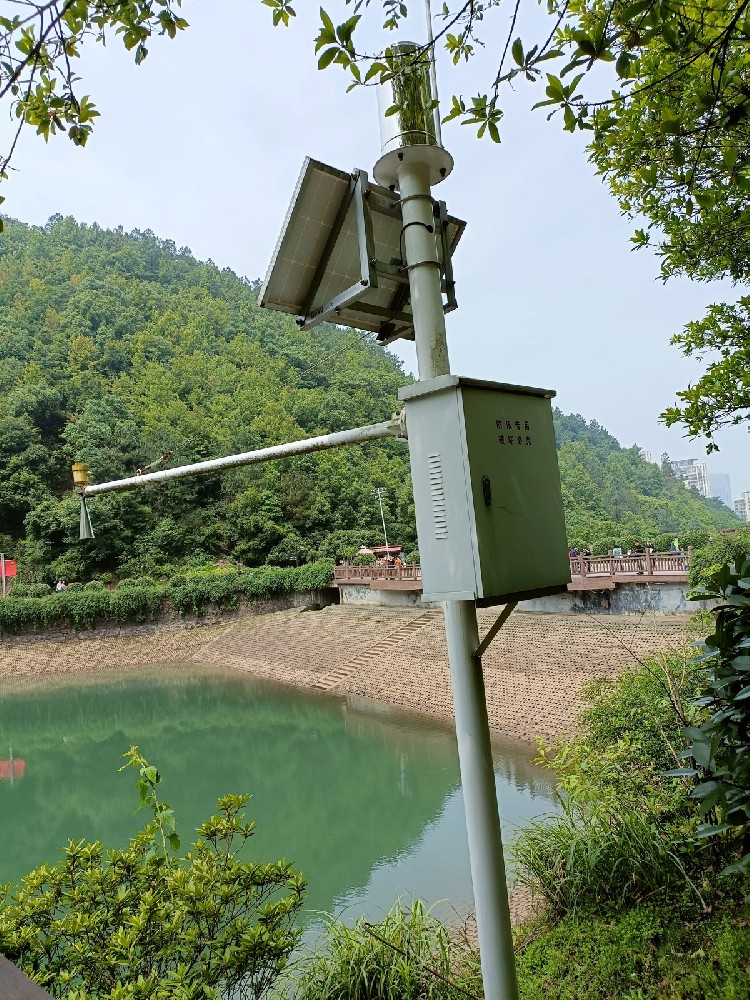
The immersed Doppler probe shown above belongs to an area-velocity monitoring arrangement. Discharge is Q = A x Vmean, where A is wetted cross-sectional area and Vmean is the representative cross-sectional mean velocity. A local or path velocity must be related to that mean using the applicable instrument and site method.
As a hypothetical calculation, 0.5 m2 of wetted area at a verified mean velocity of 0.4 m/s gives 0.2 m3/s. Using the full-pipe area for a partly filled pipe would give the wrong result. Keep the channel or pipe shape and level reference with the configuration.
| Arrangement | Main site information | Acceptance concern |
|---|---|---|
| Clamp-on transit time | Pipe dimensions, material, lining and operating condition | Acoustic path, coupling and suitable flow profile |
| Immersed Doppler | Depth, reflectors, deposits and velocity distribution | Submergence, signal quality and relation to mean velocity |
| Radar surface velocity | Surface condition, viewing geometry and section shape | Surface-to-mean relationship and level reference |
| Level measurement only | Datum and water-surface distance or depth | Not a flow result without a valid hydraulic relationship |
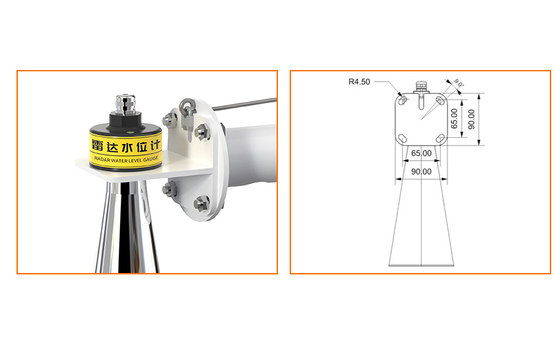
The radar mounting example above illustrates the level-measurement alternative. For tank or hydrology work, see the radar water-level sensor. Do not assign a level sensor's millimetre specification to a complete discharge measurement.
The NiuBoL Doppler velocity meter combines acoustic velocity observation with pressure-based depth measurement. Its unidirectional velocity range is 0.03-5 m/s, its level range is 0.03-5 m, and it uses DC 10-30 V supply with RS485 Modbus RTU. It has an IP68 enclosure.
Those specifications describe an immersed instrument, not an externally clamped transit-time pipe meter. Verify section geometry, minimum depth, direction and expected deposits before selecting it. Its sensor range does not establish the accuracy of an installed discharge calculation.
Check reported velocity, depth and discharge as separate fields, including units and timestamps. Confirm the receiver has not converted m3/s into m3/h incorrectly or confused an accumulated volume with an instantaneous flow rate.
Use an appropriate reference comparison over relevant operating conditions. A stable display or a successful Modbus response is not a flow calibration. Include deposits, acoustic surfaces, mounting and cable condition in the service plan; no moving rotor does not mean no maintenance.
No. External clamp-on, wetted and other acoustic arrangements exist. Identify the actual method and installation rather than inferring it from ultrasonic in the product name.
No. Electromagnetic measurement is a different principle and should not be described as a turbine or another moving-rotor method. Compare each actual design rather than assigning shared wear claims.
Suitability depends on obtaining a usable reflected acoustic signal. Where reflectors are insufficient, assess another method rather than assuming the advertised velocity range guarantees a reading.
Only where discharge is derived through a valid, applicable hydraulic relationship, such as a characterised structure or rating. A level value by itself does not determine flow for every channel.
Send NiuBoL the full-pipe or free-surface condition, dimensions, liquid, expected velocity/depth, deposits, installation access and required records. State whether the task is an operational trend, water balance or a separately specified metering requirement.
Select ultrasonic water flow meters by acoustic method and site geometry. Distinguish transit-time, immersed Doppler and radar alternatives, then verify how velocity becomes discharge. Correct units, usable signals and a valid cross-section model matter more than a universal accuracy or maintenance promise.
Prev:Dissolved Oxygen Probe Readings: Units, Saturation and Calibration Checks
Next:Water Tank Level Sensor Types: Compare Seven Measurement Methods
Related recommendations
Sensors & Weather Stations Catalog
 Agriculture Sensors and Weather Stations Catalog-NiuBoL.pdf
Weather Stations Catalog-NiuBoL.pdf
Agriculture Sensors Catalog-NiuBoL.pdf
Water Quality Sensor Catalog-NiuBoL.pdf
Related products
 Combined air temperature and relative humidity sensor
 TDR Soil Moisture & Temperature Sensor for irrigation| RS485 |4-20mA| NBL-S-THR
 Soil pH sensor RS485 soil Testing instrument soil ph meter for agriculture |NBL-S-PH
 Wind Speed sensor Output Modbus/RS485/Analog/0-5V/4-20mA
 Tipping bucket rain gauge for weather monitoring auto rainfall sensor RS485/Outdoor/stainless steel
 Pyranometer Solar Radiation Sensor 4-20mA/RS485


Screenshot, WhatsApp to identify the QR code
WhatsApp number:+8615367865107
(Click on WhatsApp to copy and add friends)

