





— Blogs —
—Products—
 Consumer hotline +8618073152920
WhatsApp:+8615367865107
Address:Room 102, District D, Houhu Industrial Park, Yuelu District, Changsha City, Hunan Province, China
Product knowledge
Time:2025-10-18 10:00:04 Popularity:1472
The cup anemometer working principle is to convert wind-driven rotor motion into a wind-speed signal using the instrument's calibration relationship. A three-cup rotor responds to horizontal airflow without measuring its direction. Mechanical starting resistance and response time remain relevant even when the final output is digital.
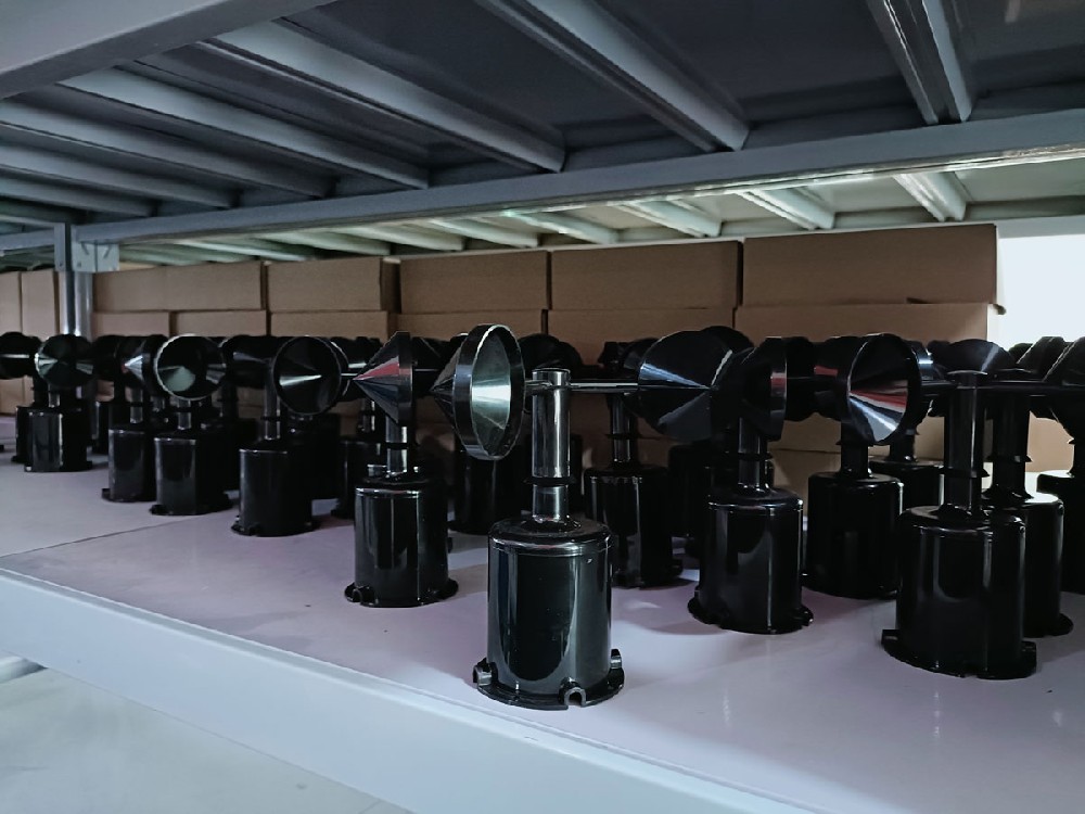
Wind produces different aerodynamic forces on the exposed cup surfaces, creating torque around the vertical shaft. The internal sensing circuit detects rotor motion and converts it into an electrical output. The receiving equipment interprets that output as wind speed in the specified unit.
The relationship belongs to the actual instrument. It is not enough to count rotations and apply an arbitrary multiplier. Changing cup geometry, damaging the rotor or using the wrong conversion can change the result even when the assembly appears to turn normally.
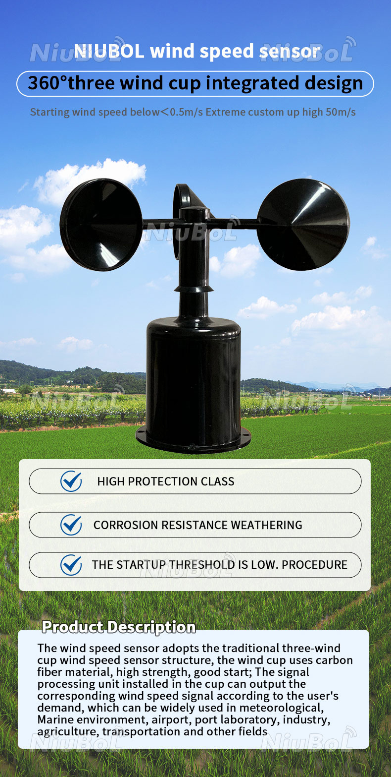
For the pulse-output NiuBoL NBL-W-SS, the conversion is W = 0 when frequency f = 0; otherwise W = 0.1 + 0.0875 x f. W is wind speed in m/s and f is frequency in Hz. This model-specific relationship is not simply W = K x f.
For example, 100 Hz gives 8.85 m/s using that relationship. This is an illustrative signal conversion, not a wind-tunnel calibration result. Apply the pulse formula only to the appropriate output version; an RS485 or analog receiver needs its own specified decoding or scaling.
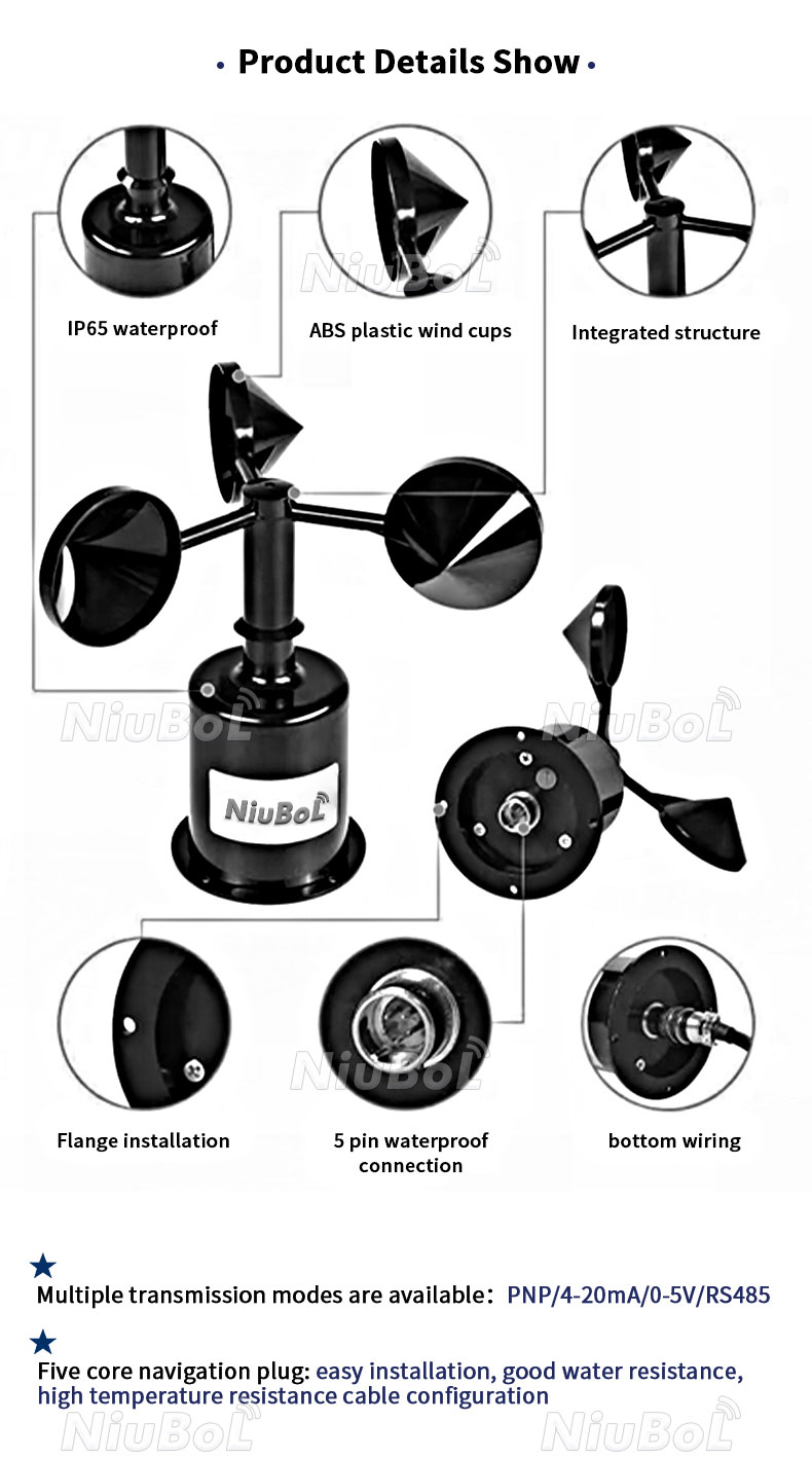
The NBL-W-SS three-cup sensor has a starting wind speed of 0.5 m/s or less and a resolution of 0.1 m/s. Resolution describes the reported increment, not the ability to start from rest at that wind speed. A zero reading below the starting condition cannot establish perfectly still air.
| NBL-W-SS item | Specification | Interpretation |
|---|---|---|
| Range options | 0-45 m/s or 0-70 m/s | Select the ordered span for the expected exposure |
| Accuracy | +/-(0.3 + 0.03V) m/s | V is wind speed; this is not a constant percentage |
| Resolution | 0.1 m/s | Not a starting-speed or accuracy specification |
| Starting speed | 0.5 m/s or less | Mechanical response matters in light wind |
| Protection | IP65 | Does not establish ice-free rotation or immersion suitability |
| Output options | RS485 Modbus RTU, analog or pulse | Match the offered version to the receiving input |
At V = 10 m/s, the accuracy expression gives +/-(0.3 + 0.3), or +/-0.6 m/s. That calculation explains the specification; it does not add allowances for siting, icing or an incorrectly configured receiver.
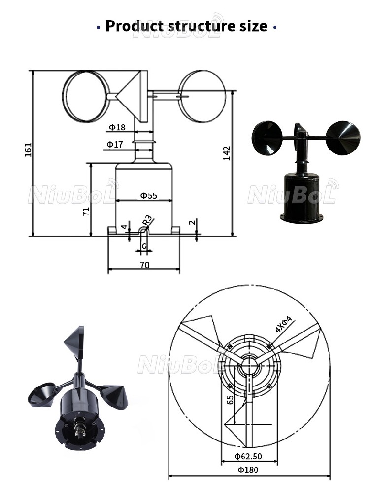
A mechanical rotor cannot respond instantaneously to a change in airflow. Bearings and rotor inertia affect its response. A digital output reports the instrument's result; it does not remove those mechanical characteristics or prove suitability for turbulence research.
Keep sampling and statistics distinct. A one-minute saved wind-speed value is not automatically a gust or an average over a defined period. Before specifying short-duration peaks, establish the required response, sampling and calculation method for the complete acquisition system.
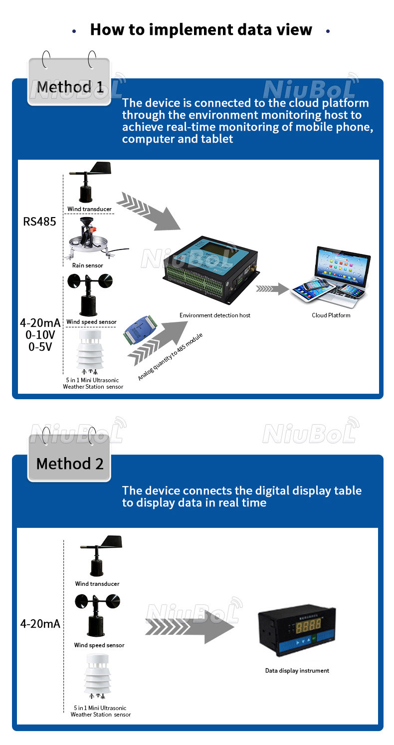
The cup sensor supplies wind speed. Pair it with a suitable direction instrument, such as the NBL-W-DS wind vane, when direction is required. The vane needs its own orientation and receiver mapping; it is not an extra quantity calculated from cup rotation.
A logger, PLC or RTU reads the chosen output. RS485 Modbus RTU requires matching serial and register settings; analog inputs require matching scaling; pulse inputs require the correct conversion. Neither an RS485 connector nor a radio gateway means that the cup sensor connects directly to a cloud service.
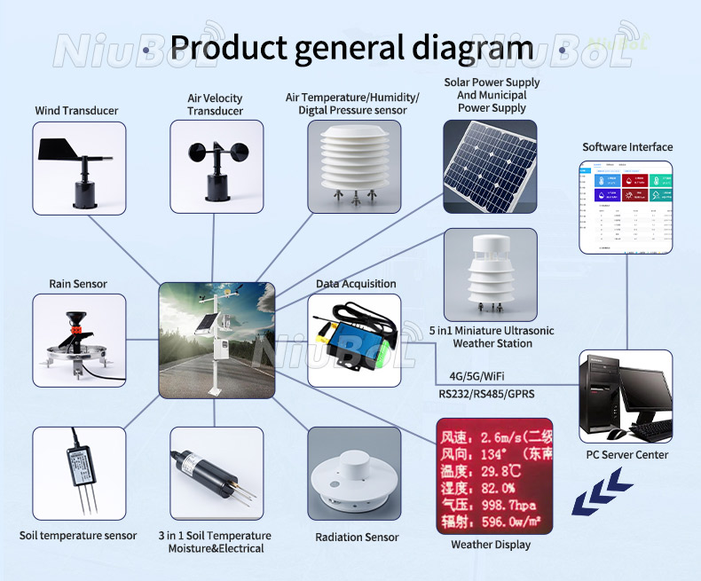
Inspect damaged cups, contamination, cable strain and abnormal rotor movement when observations become implausible. A rotor that is obstructed can remain electrically connected while under-reporting wind. Compare readings under suitable conditions before changing the conversion to hide the discrepancy.
Do not add lubricant, dismantle bearings or assume a heating function without the procedure for the delivered instrument. IP65 describes enclosure protection, not freedom from inspection. For freezing exposure, establish the required anti-icing arrangement separately rather than assuming an operating-temperature range guarantees an ice-free rotor.
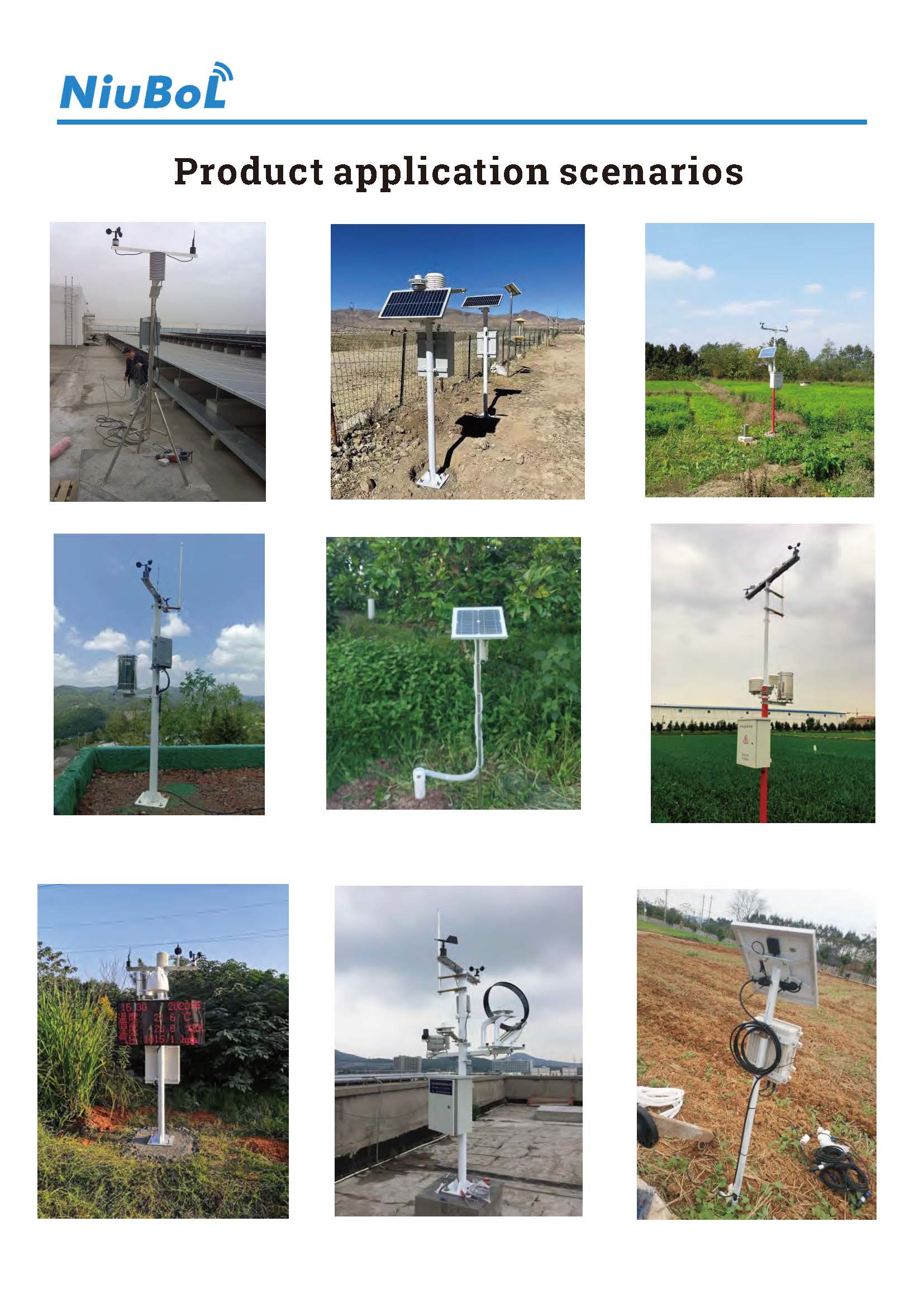
Cup instruments can suit routine outdoor wind observations when the range, exposure and service access match the task. Very low air-speed work, enclosed-duct measurements or specialised turbulence measurements need a separate suitability assessment. The familiar shape alone does not make one model appropriate for every airflow application.
No. It measures speed. A separate vane or a combined instrument is needed when the project requires direction as well.
No. Use it for the applicable pulse version. Analog and RS485 versions provide different signal forms and require their own receiving configuration.
No. Resolution, accuracy and starting speed describe different properties. Use the model's accuracy expression at the relevant speed and assess installation effects separately.
No. It can avoid some analog conversion steps, but rotor condition, exposure, response and register interpretation still matter. Changing the interface does not remove mechanical limitations.
Send NiuBoL the expected wind range, receiving input, supply, cable length and exposure. Identify any required gust statistics, calibration documents or freezing-weather operation so those needs can be assessed explicitly.
Understanding the cup anemometer working principle helps separate rotor behaviour from signal processing. Use the correct conversion and distinguish resolution, accuracy and starting speed. Select the instrument for the actual airflow task, with a separate direction channel and suitable acquisition where required.
Related recommendations
Sensors & Weather Stations Catalog
 Agriculture Sensors and Weather Stations Catalog-NiuBoL.pdf
Weather Stations Catalog-NiuBoL.pdf
Agriculture Sensors Catalog-NiuBoL.pdf
Water Quality Sensor Catalog-NiuBoL.pdf
Related products
 Combined air temperature and relative humidity sensor
 TDR Soil Moisture & Temperature Sensor for irrigation| RS485 |4-20mA| NBL-S-THR
 Soil pH sensor RS485 soil Testing instrument soil ph meter for agriculture |NBL-S-PH
 Wind Speed sensor Output Modbus/RS485/Analog/0-5V/4-20mA
 Tipping bucket rain gauge for weather monitoring auto rainfall sensor RS485/Outdoor/stainless steel
 Pyranometer Solar Radiation Sensor 4-20mA/RS485


Screenshot, WhatsApp to identify the QR code
WhatsApp number:+8615367865107
(Click on WhatsApp to copy and add friends)

