





— Blogs —
—Products—
 Consumer hotline +8618073152920
WhatsApp:+8615367865107
Address:Room 102, District D, Houhu Industrial Park, Yuelu District, Changsha City, Hunan Province, China
Product knowledge
Time:2025-10-18 09:51:41 Popularity:1200
An analog vs digital anemometer comparison is primarily an output-interface decision, not a choice between inaccurate and error-free wind measurement. A 4-20 mA, voltage or RS485 Modbus RTU version must match the receiving input and installation. Digital communication can detect some transmission faults, but it does not remove sensor error, rotor limitations or configuration mistakes.
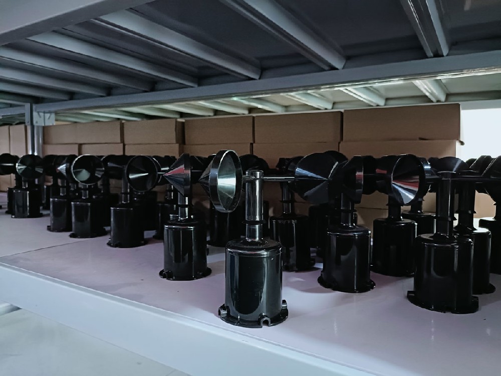
A cup instrument can provide an analog signal or a digital message while retaining the same mechanical measuring principle. An ultrasonic instrument can also have different output options. Changing the interface does not turn a cup sensor into an ultrasonic sensor or establish a different accuracy specification.
First identify the required wind range and observation method. Then choose the output for the PLC, RTU or data logger. When replacing an installed instrument, check its complete order code rather than assuming that the same model family always has the same wiring and signal.
| Output | Receiver requirement | Check before acceptance |
|---|---|---|
| 4-20 mA | Compatible current input and sufficient loop voltage | Input mode, load, supply and range scaling |
| Voltage | Matching voltage input and suitable reference wiring | Input impedance, grounding and full-scale value |
| RS485 Modbus RTU | Supported serial settings and register decoding | Address, data representation, scaling and stale-data status |
| Pulse | Compatible frequency or counter input | Electrical pulse type and model-specific conversion |
A current loop can be useful over a cable route where a voltage signal would be harder to manage, provided the complete load remains within the transmitter's capability. Neither analog output has an automatic distance limit of 30 or 50 metres. Cable, supply, receiver and electrical conditions determine suitability.
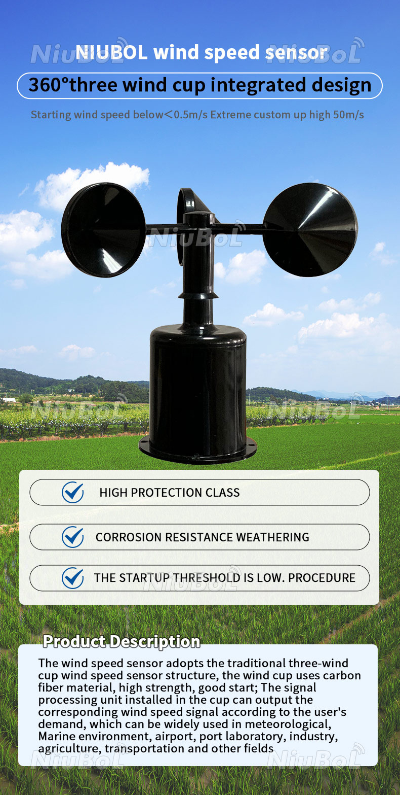
The NiuBoL NBL-W-SS offers 0-45 m/s and 0-70 m/s ranges with output versions including current, voltage, pulse and RS485. For a linearly scaled 4-20 mA version, wind speed equals (I - 4) / 16 multiplied by the ordered full-scale speed, with I in mA.
At 12 mA, that gives 22.5 m/s for a 0-45 m/s span or 35 m/s for a 0-70 m/s span. These are conversion examples, not field wind observations. A receiver configured for the wrong span can show a plausible but substantially wrong speed.
The NBL-W-SS current-output load limit is 250 ohms or less; the voltage-output load is 1 kilohm or greater. Match the supply to the selected version. These electrical limits should not be transferred to another wind instrument merely because it uses the same signal name.
RS485 uses differential electrical signalling, but it still needs suitable wiring, grounding, topology and protection. Modbus RTU adds addressed messages and CRC checking. A CRC can identify a corrupted frame; it cannot establish that the correct register, unit or sensor location was used.
Read the instrument's configured address and communication settings. Verify the returned value against the expected scale and data type. Do not assume automatic device identification, a universal register map or simultaneous analog and digital outputs unless the selected configuration provides them.
Make a failed request visible as a communications fault. Repeating the last good speed without marking it stale can conceal an interrupted cable. Keep the observation time distinct from the time when an application last refreshed its display.
Test the offered instrument through the intended receiver and a representative cable route. For analog acquisition, compare the signal at the receiving input with the decoded engineering value. For serial acquisition, inspect successful reads, timeouts and channel interpretation during normal site operation.
Investigate supply voltage at the instrument, grounding and nearby electrical equipment if results become unstable. A digital link is not immune to electromagnetic disturbance, and an analog fluctuation is not automatically a cable fault. The sensor may be observing real wind changes.
The NBL-W-SS and separate NBL-W-DS direction sensor have IP65 protection. That enclosure rating does not replace cable-entry protection, surge assessment or inspection of moving parts. It also does not establish a lightning-survival guarantee for the complete station.
An existing PLC with spare current inputs may favour a compatible analog version. A station already polling supported Modbus sensors may favour serial integration. Include receiver modules, configuration and testing when comparing quotations; there is no universal percentage saving from choosing digital.
A converter can sometimes bridge an interface mismatch, but it adds another supply, scaling and fault-handling boundary. Test one complete replacement channel before ordering many instruments. Keep the original units and recording definition so the upgrade does not silently change the historical series.
Not by itself. It changes data transport and receiving requirements. Sensor performance, exposure and configuration still contribute to the final measurement.
No. It can be appropriate when supply, total load, cable and receiver are compatible. Assess the actual circuit instead of applying a generic short-distance rule.
Not on the same shared bus when the receiver must address them separately. Assign suitable unique addresses and confirm the remaining serial settings and register interpretation.
Only if simultaneous outputs are explicitly part of that configuration. A product listing several output options does not establish that every option is active on one unit.
Send NiuBoL the sensor range, existing input type, supply, cable route and required records. For serial integration, include the receiver's supported protocol and register requirements; for replacement, include the installed order code.
Resolve an analog vs digital anemometer choice through the complete receiving channel. Check scaling, electrical limits and fault indication rather than assuming one interface guarantees accuracy. A successful upgrade preserves the meaning of the wind record as well as the connection.
Prev:Water Tank Level Sensor Types: Compare Seven Measurement Methods
Next:Cup Anemometer Working Principle: What Rotation Can and Cannot Measure
Related recommendations
Sensors & Weather Stations Catalog
 Agriculture Sensors and Weather Stations Catalog-NiuBoL.pdf
Weather Stations Catalog-NiuBoL.pdf
Agriculture Sensors Catalog-NiuBoL.pdf
Water Quality Sensor Catalog-NiuBoL.pdf
Related products
 Combined air temperature and relative humidity sensor
 TDR Soil Moisture & Temperature Sensor for irrigation| RS485 |4-20mA| NBL-S-THR
 Soil pH sensor RS485 soil Testing instrument soil ph meter for agriculture |NBL-S-PH
 Wind Speed sensor Output Modbus/RS485/Analog/0-5V/4-20mA
 Tipping bucket rain gauge for weather monitoring auto rainfall sensor RS485/Outdoor/stainless steel
 Pyranometer Solar Radiation Sensor 4-20mA/RS485


Screenshot, WhatsApp to identify the QR code
WhatsApp number:+8615367865107
(Click on WhatsApp to copy and add friends)

