





— Blogs —
—Products—
 Consumer hotline +8618073152920
WhatsApp:+8615367865107
Address:Room 102, District D, Houhu Industrial Park, Yuelu District, Changsha City, Hunan Province, China
Product knowledge
Time:2025-10-13 17:00:40 Popularity:2959
How an anemometer works depends on its sensing method. A cup instrument converts rotor movement into wind speed; an ultrasonic instrument compares sound travel along measurement paths. A wind vane measures direction separately unless it is part of an integrated instrument. Neither a speed reading nor a two-axis wind sensor automatically provides three-dimensional airflow.
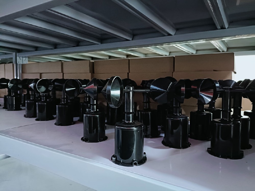
An anemometer is an instrument for measuring air speed. In an outdoor station, its output becomes useful only when the exposure, units and record definition are known. The same instrument reading can support a field observation or an operational review, but the equipment is not a weather forecast or an independent safety system.
A cup rotor turns because of the different aerodynamic forces on its surfaces. The instrument detects rotation and converts it using its calibration relationship. The receiving device may obtain pulses, an analog value or digital data, depending on the selected transmitter. Rotation rate should not be converted with an arbitrary factor taken from another model.
A cup sensor has a starting threshold and mechanical behavior that matter at low speed and during changing wind. Below the useful operating conditions, a stationary rotor should not automatically be interpreted as proof of calm air. Inspect the rotor and bearings if a channel remains at zero while other observations indicate movement.
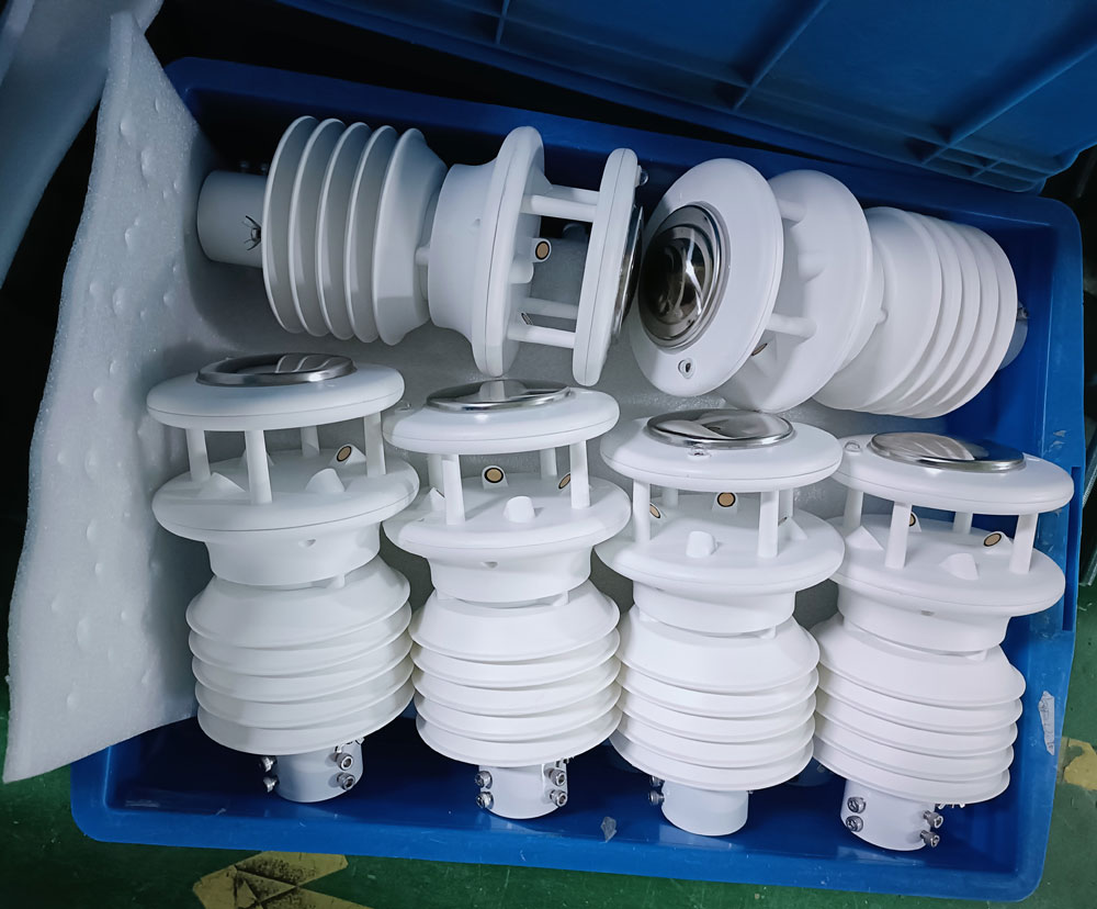
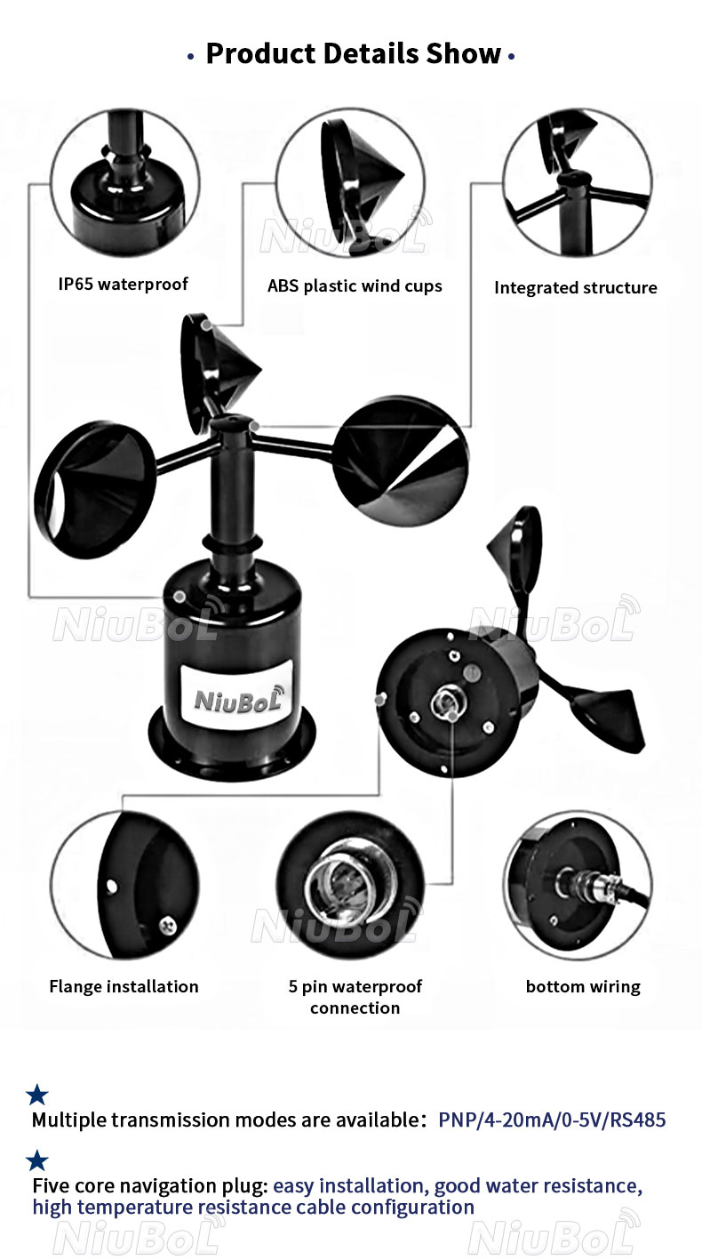
The integrated weather instruments above illustrate a different construction. Their housings can include wind and other environmental channels, but the channel list must be checked for the exact model. Housing shape alone does not establish whether it measures precipitation, particles or vertical wind.
A wind vane aligns with airflow and converts angular position into a signal. A cup anemometer paired with a vane therefore provides speed and direction through separate measurements. The NiuBoL NBL-W-SS is a wind-speed instrument; the NBL-W-DS provides wind direction.
Install the direction instrument against the required north reference and document any offset. A north wind conventionally describes wind arriving from the north, not travelling toward it. Confirm the receiving platform uses the same convention before using a direction arrow in an operational display.
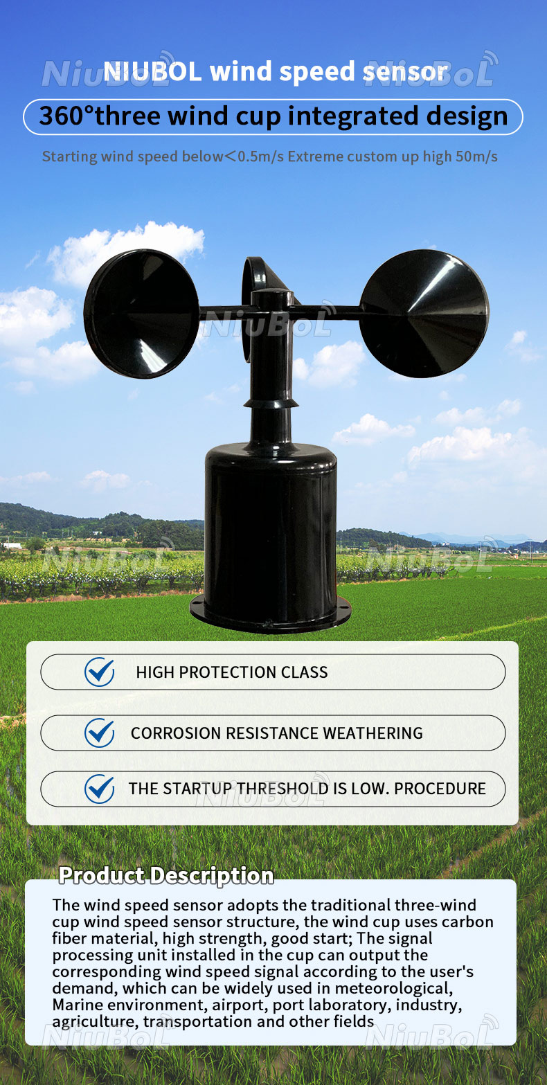
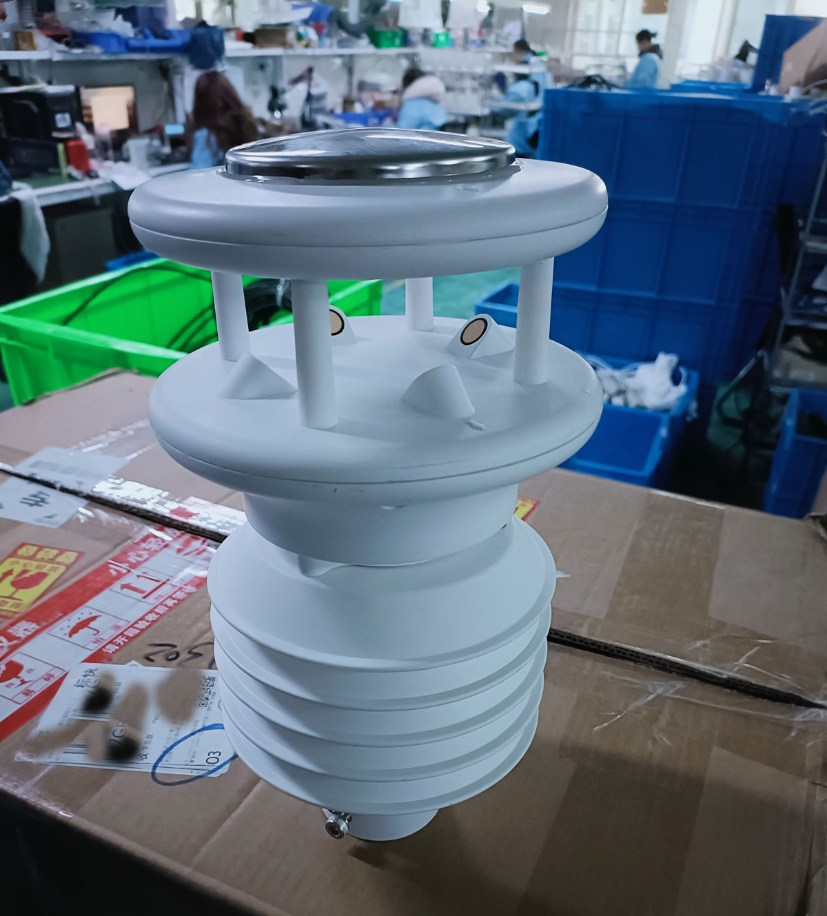
Wind changes the acoustic travel time differently along and against a measurement path. An ultrasonic instrument combines the results from its configured paths to calculate wind components, speed and direction. A two-axis horizontal instrument does not acquire a vertical component simply because its output is digital.
Removing rotating cups and a vane removes those moving assemblies. It does not prevent ice, insects, deposits or physical obstruction from affecting the acoustic path. Inspect the transducers and mounting, and confirm whether heating is available and required for the intended climate.
| NiuBoL option | What it supplies | Relevant configuration limit |
|---|---|---|
| NBL-W-SS | Three-cup wind-speed measurement | IP65; select the actual range and electrical output to match the receiver. |
| NBL-W-DS | Wind direction over 0-360 degrees; stated accuracy +/-3 degrees | IP65; mounting orientation and the selected output affect integration. |
| NBL-W-21GUWS | Horizontal wind speed 0-60 m/s and direction 0-359 degrees; RS485 output | DC 12-24 V; IP65; -20 to 80 degrees C operating temperature; optional 3 W heating. |
The NBL-W-21GUWS is a separate wind-instrument configuration from the integrated heads pictured on this page. Match the model, protocol settings and register map rather than transferring specifications between similar-looking products.
Sampling, averaging and reporting are different operations. A logger can poll a sensor frequently but save a longer-period record. An interval mean, latest sample and gust value can differ without any instrument failure. Agree on the calculation and observation interval, then test the exported fields.
Check units as well. One m/s equals 3.6 km/h, so 5 m/s equals 18 km/h. A receiving system configured in the wrong unit can create a large apparent disagreement even when the electrical signal is correct.
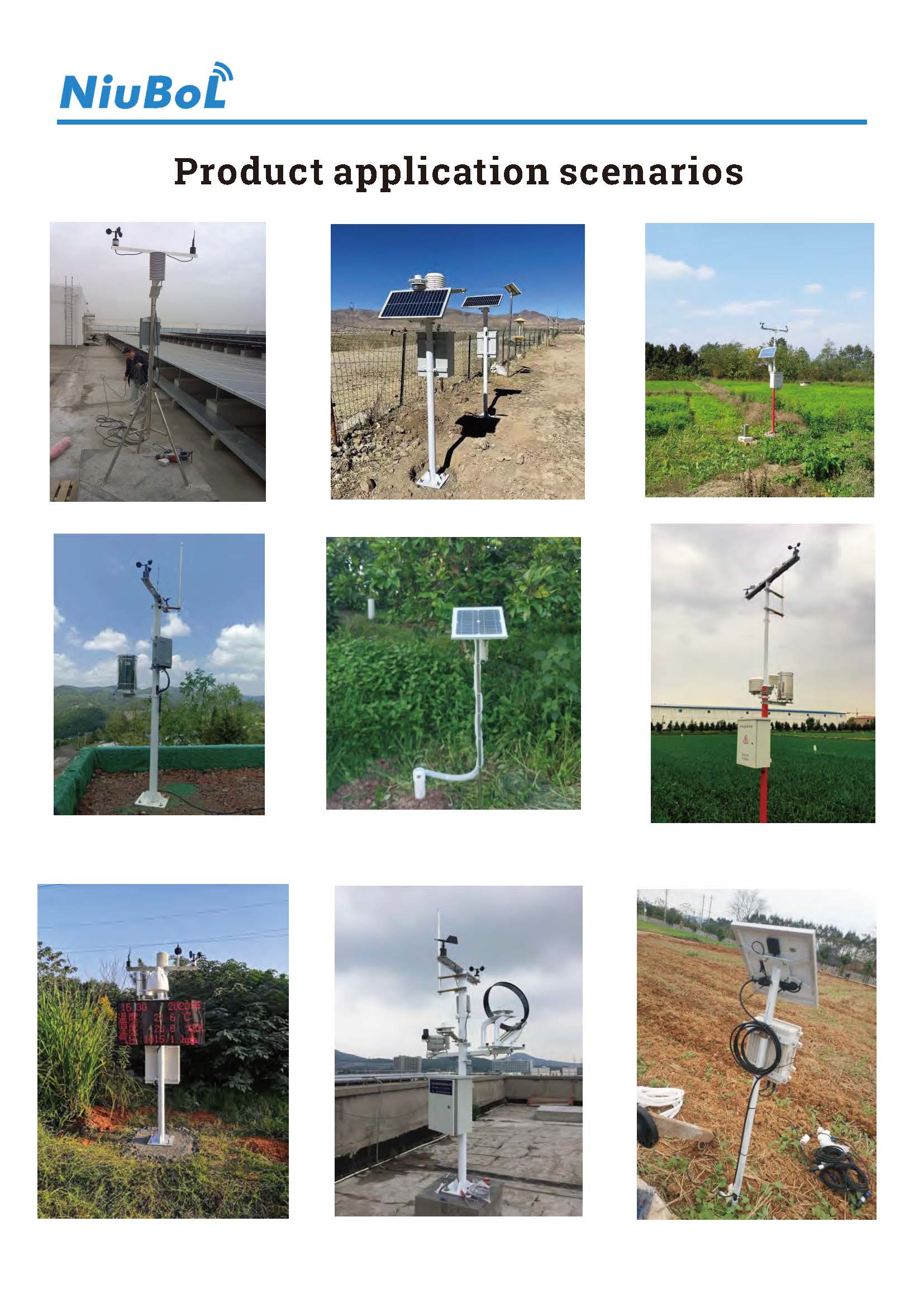
A sensor behind a building or among branches measures the disturbed local flow. Choose the location and height for the required observation, whether reference weather, a crop environment or a particular structure. Results from different exposures should not be compared as if they describe the same wind.
For spray-related assessment, wind is one input alongside the relevant operating restrictions and conditions. For lifting equipment, use the equipment's approved wind-monitoring and protection arrangements. An outdoor sensor does not provide hours of advance warning merely by measuring a current gust.
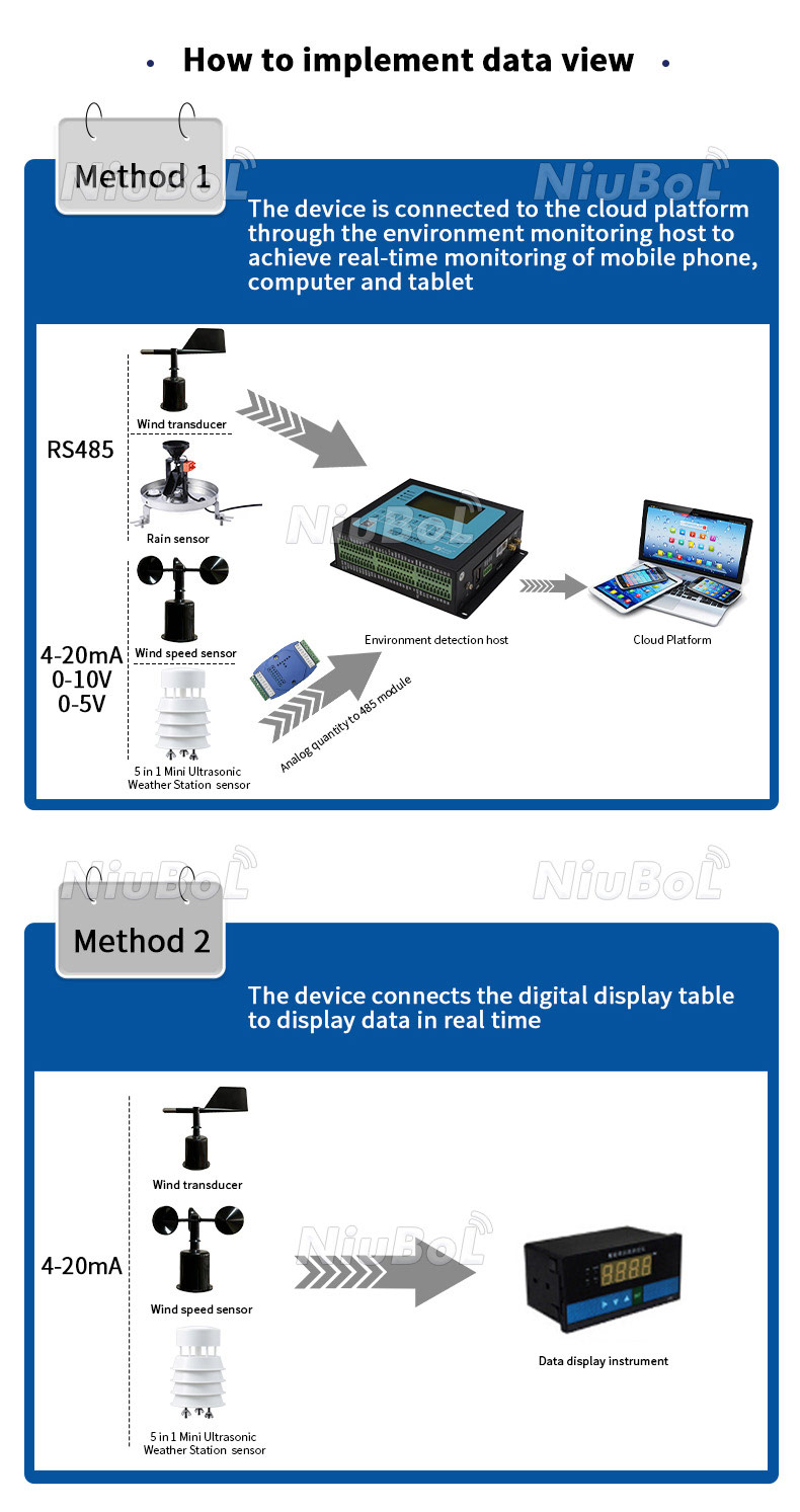
For a PLC, RTU or data logger, verify supply, signal version, scaling and invalid-value handling. RS485 Modbus RTU requires a matching register interpretation, not just an RS485 terminal. Test a disconnected instrument so a missing update does not remain displayed indefinitely as valid wind.
No. A cup wind-speed sensor needs a separate direction instrument if direction is required. Some ultrasonic instruments combine both measurements, subject to their actual axis configuration.
Not unless it includes the required vertical measurement capability. Specify the components needed and request model-specific evidence rather than assuming all ultrasonic instruments are three-axis devices.
No. A stopped rotor, incorrect scaling, invalid output or stale record can also appear as zero. Check sensor status and field conditions before interpreting it.
Not automatically. Compare exposure, response, averaging and output definitions. Where continuity matters, make an appropriate overlap comparison and record the configuration change.
Confirm the model, mounting, direction orientation, units and logger values. Test communication loss and inspect mechanical freedom or acoustic-path clearance. Use a suitable reference method for any required accuracy verification.
Provide the wind range, speed/direction or axis requirements, environment, mounting arrangement, available supply and receiving interface. Include heating and record requirements so the complete configuration can be assessed.
Understanding how an anemometer works starts with the quantity measured and the method used. Cups, vanes and ultrasonic paths have different roles and service requirements. Select a NiuBoL configuration around the exposure and required record, then verify the signal through to the receiving system.
 NBL-W-21GUWS-Ultrasonic-Wind-speed-and-direction-Sensor.pdf
Related recommendations
Sensors & Weather Stations Catalog
Agriculture Sensors and Weather Stations Catalog-NiuBoL.pdf
Weather Stations Catalog-NiuBoL.pdf
Agriculture Sensors Catalog-NiuBoL.pdf
Water Quality Sensor Catalog-NiuBoL.pdf
Related products
 Combined air temperature and relative humidity sensor
 TDR Soil Moisture & Temperature Sensor for irrigation| RS485 |4-20mA| NBL-S-THR
 Soil pH sensor RS485 soil Testing instrument soil ph meter for agriculture |NBL-S-PH
 Wind Speed sensor Output Modbus/RS485/Analog/0-5V/4-20mA
 Tipping bucket rain gauge for weather monitoring auto rainfall sensor RS485/Outdoor/stainless steel
 Pyranometer Solar Radiation Sensor 4-20mA/RS485


Screenshot, WhatsApp to identify the QR code
WhatsApp number:+8615367865107
(Click on WhatsApp to copy and add friends)

