





— Blogs —
—Products—
 Consumer hotline +8618073152920
WhatsApp:+8615367865107
Address:Room 102, District D, Houhu Industrial Park, Yuelu District, Changsha City, Hunan Province, China
Product knowledge
Time:2026-01-03 14:56:12 Popularity:949
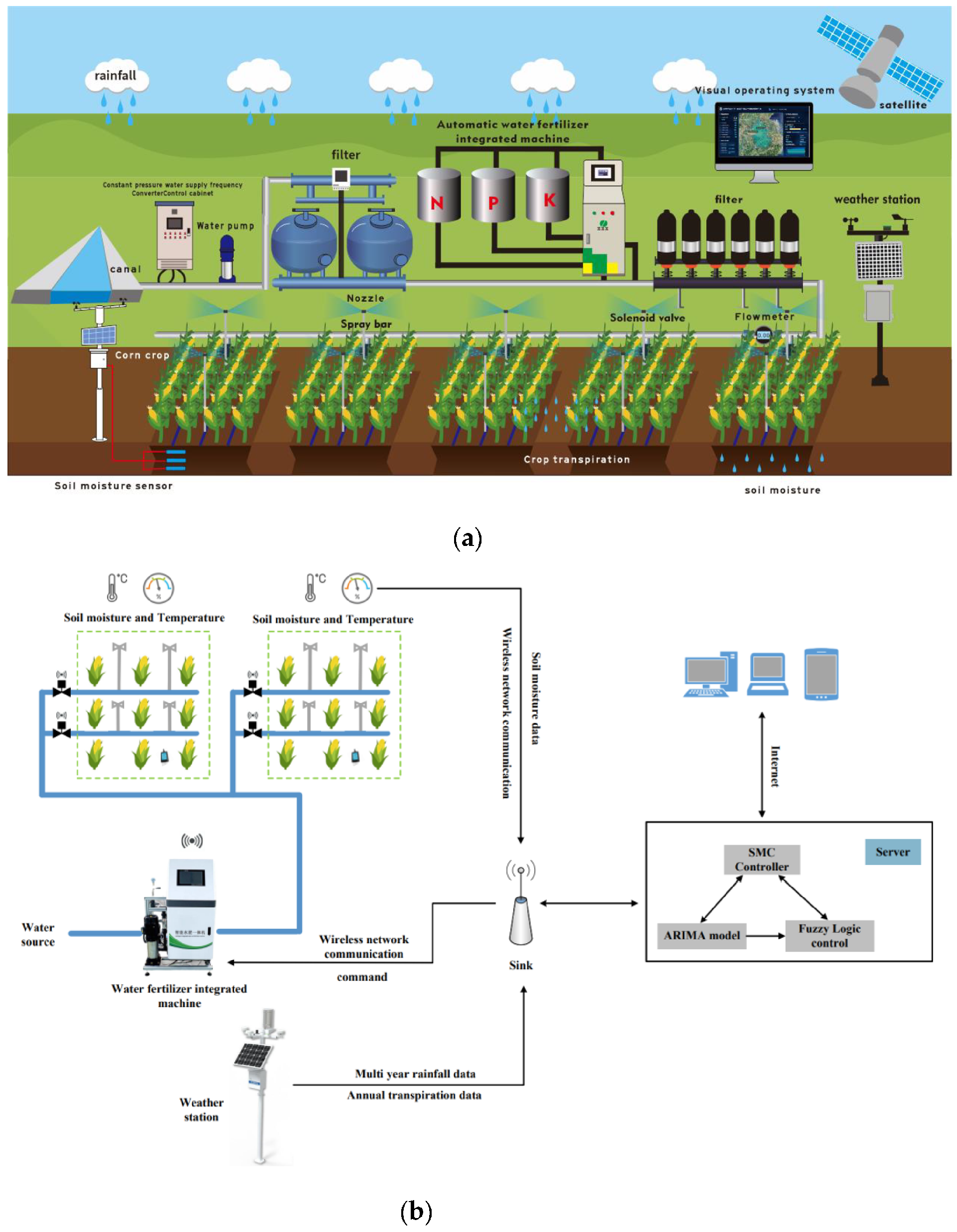
Fertigation system implementation starts with the irrigation network, not the control screen. A dosing unit can deliver the intended concentration at the headworks while distant plants receive too little water, a blocked lateral receives none, or a sensor measures an unrepresentative wet patch. Four tasks must work together: hydraulic zoning, injection and filtration, fertilizer compatibility, and field commissioning. This guide explains how to turn those tasks into decisions for a new installation or an existing drip-irrigation retrofit.
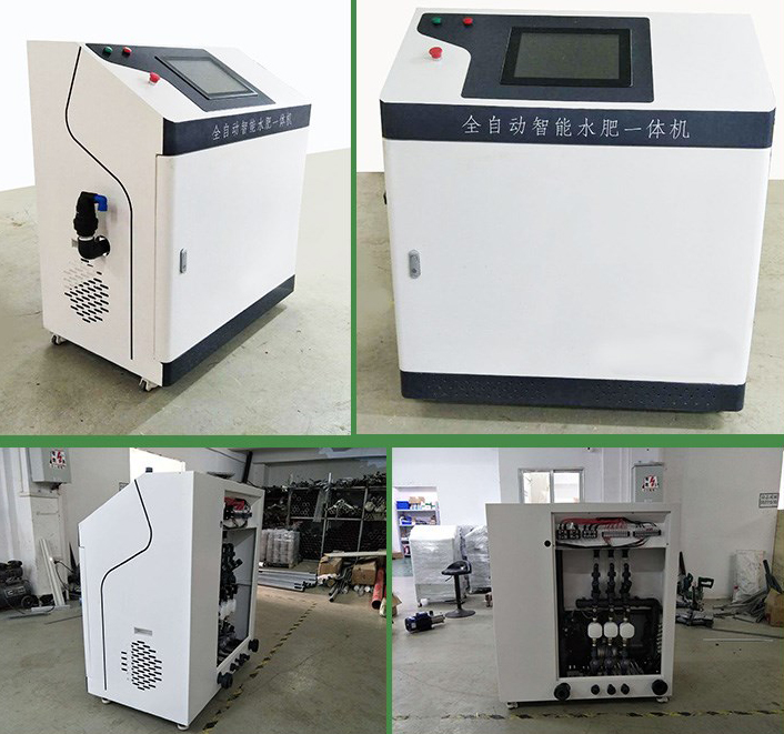
Begin with the area irrigated by each valve, the emitter model and spacing, lateral lengths, elevation differences, and the water supply available while other users are drawing water. A pump nameplate does not establish the pressure at the last emitter. Measure operating flow and pressure with the intended combination of zones open, then compare the results with the hydraulic design.
Group areas that can reasonably share a watering event. Different soils, crop stages or planting densities may need separate schedules even where one pipe can physically serve them. Conversely, splitting every row into an independently controlled zone increases valves, wiring and maintenance. The useful division is the smallest number of zones that can accommodate meaningful differences in water delivery and crop demand.
Pressure-compensating emitters can reduce discharge variation inside their specified operating range; they do not remove elevation head, friction losses or clogging. For scale, a 10 m rise requires approximately 98 kPa of additional static pressure for water, before pipe and fitting losses. This is a hydraulic calculation, not an emitter specification. Check pressure at high and low positions rather than assuming that a compensated dripper guarantees a fixed percentage of uniformity.
Soil affects the wetting pattern as well as the irrigation interval. Examine the wetted soil around several emitters after a trial run, including near a lateral end. A narrow wetted column may miss part of an orchard root zone; ponding may indicate application faster than local infiltration. Neither problem is corrected by adding another remote-control function. FAO's drip-irrigation guidance describes the interaction between emitter discharge, soil and wetting pattern.
Separate a command from confirmation of its result. A valve-open command is not proof of water flow. An energized pump contact is not proof that the supply tank contains water. The control design should identify which measurements allow fertilizer injection and which conditions stop it. Typical inputs include verified irrigation flow, pressure within the designed range and available stock solution, with the exact devices selected for the installation.
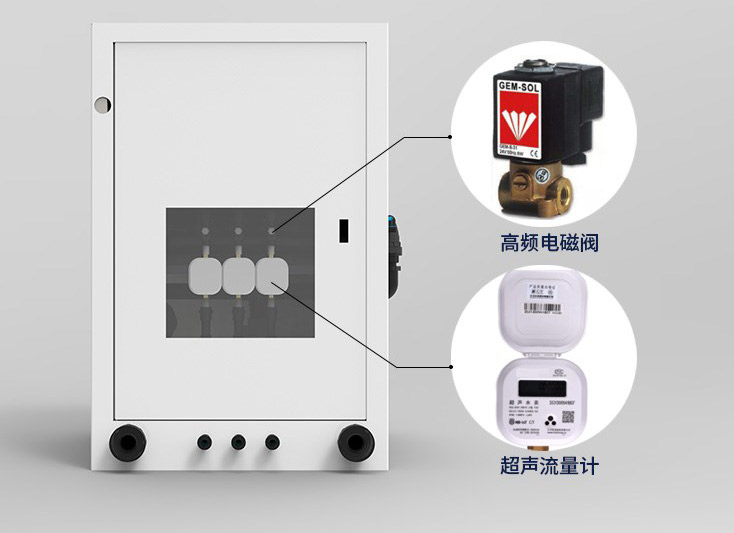
The electrical cabinet must match the loads. A logger relay may provide a control contact for an external starter or valve interface; it should not be assumed to drive a pump motor directly. Have the electrical designer define isolation, overload protection and the de-energized state of each output. Keep the local means of stopping injection accessible even when the phone or remote server is unavailable.
For an RS485 Modbus RTU monitoring network, prepare a point list before wiring: sensor address, parameter, unit, scaling and the controller input that uses it. Soil moisture may help schedule irrigation, but a failed soil reading should not be treated as zero moisture and trigger unlimited watering. Decide whether the affected zone will revert to a bounded schedule or require operator approval. Test that behavior with the agronomist and controls contractor.
Obtain a water analysis and inspect the source over its expected operating conditions. Suspended mineral particles, algae and dissolved substances that can precipitate create different problems. A screen removes particles above its effective opening; it does not remove dissolved hardness. A sand separator is not a substitute for handling light organic material. Select treatment and final filtration against the emitter supplier's requirements and the actual water, rather than imposing the same three-filter sequence on every site.
Allow for filter pressure loss at operating flow and for cleaning or backwashing. Include pressure measurement on both sides where differential pressure is used to assess filter loading. A rising pressure difference at the same flow suggests loading, but a falling flow can hide that increase. Keep flow, inlet pressure and outlet pressure in the same operating record so the readings can be interpreted together.
A Venturi injector requires a suitable pressure differential. A metering pump has its own capacity and discharge-pressure limits. In either case, check performance at the smallest and largest intended zone flows; an injector that works during a large-zone test may be unsuitable when a small zone operates alone. The fertilizer delivery rate must remain controllable across that range without destabilizing irrigation pressure.

Choose fertilizers that are suitable for the selected injection equipment and crop program. A clear stock solution is useful, but clarity at preparation does not prove that the mixture will remain clear after dilution into the irrigation water. Temperature, concentration and the source-water chemistry can change precipitation risk. Request compatibility guidance for the actual products instead of judging only by whether a fertilizer is liquid or powder.
Keep incompatible concentrated stocks separate. Calcium-containing concentrates and phosphate-containing concentrates, for example, require particular attention because precipitation can occur when incompatible solutions meet. Separate tanks alone do not prove that the final mixed irrigation solution is suitable. The fertilizer specialist should review the injection arrangement, final dilution and water analysis. Do not use an online EC reading as a chemical compatibility test.
A small compatibility assessment can identify obvious cloudiness or sediment under representative conditions, but it does not establish agronomic suitability, material compatibility or safe chemical handling. Follow the fertilizer supplier's procedures and safety information. Do not introduce a universal acid-cleaning recipe, concentration or mesh size for all installations. Reclaimed organic liquids may need treatment beyond filtration and may be unsuitable for particular emitters.
Record the fertilizer product, stock concentration, preparation date and dosing setting for each trial. Without the stock concentration, a statement such as "inject 20 litres" gives no nutrient mass. If a formulation changes, the previous injection setting cannot automatically be reused. EC and pH are useful mixture indicators, but neither identifies every nutrient or confirms that the crop has received the intended nutrient balance.
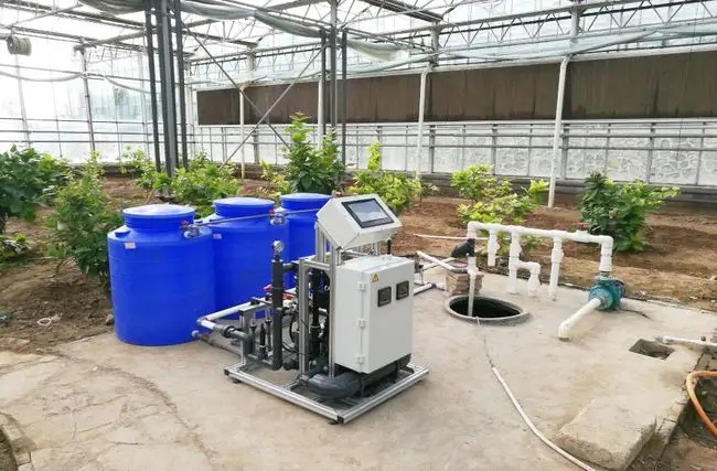
NiuBoL soil sensors fit on the observation side of the installation. Place them where they can show whether the irrigation event reached the managed root layer, not merely beside the nearest pipe or power source. Include a deeper observation point when the project needs to investigate water moving below the active root zone. Record the horizontal distance from the emitter so subsequent readings are comparable.
The NBL-S-TMCS soil temperature, moisture, EC and salinity sensor can supply several related measurements. Its channels should still be interpreted separately: a change in soil moisture alters the electrical environment around the electrodes, so a soil EC change is not a direct measurement of fertilizer consumption.
| NBL-S-TMCS parameter | Value and installation implication |
|---|---|
| Soil temperature | -40 to 80 degrees C; resolution 0.1 degrees C; accuracy +/-0.5 degrees C. |
| Volumetric moisture | 0-100%; resolution 0.1%. A displayed decimal is not a field accuracy guarantee. |
| Electrical conductivity | 0-10,000 uS/cm; resolution 1 uS/cm. Compare readings under comparable moisture conditions. |
| Conductivity temperature compensation | 0-50 degrees C; do not confuse this with the temperature measurement range. |
| Integration and installation | RS485 Modbus communication; IP68; standard cable length 5 m. Insert all sensing probes into the medium and protect cable joints separately. |
For commissioning, compare several representative watering events with the soil response. A rapid wetting signal at one point does not prove that the whole zone is uniform. If plants at the end of a row remain dry while the sensor stays wet, inspect delivery and placement before changing the moisture threshold. Send NiuBoL the zone map, soil type, required depths and receiving controller details when selecting the monitoring package.
Flush construction debris through the designated outlets, then test each zone with clean water. Measure pressure and collect emitter discharge for equal durations at representative positions, including hydraulically difficult locations. Keep the sampling method consistent. Repair blocked or damaged outlets and investigate low-pressure sections before using concentration control to compensate for an uneven delivery network.
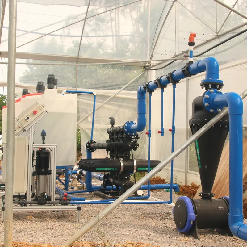
A useful calculation is low-quarter distribution uniformity: divide the mean discharge of the lowest quarter of sampled emitters by the mean of all sampled emitters. UC Cooperative Extension describes this method in Irrigation Distribution Uniformity for Adjusting Irrigation Timing. In a hypothetical 16-emitter test, a lowest-quarter mean of 1.5 L/h and an overall mean of 2.0 L/h give 75%. This is an illustrative result, not an acceptance target. It shows why a correct headworks concentration can still produce unequal nutrient delivery. Agree the required uniformity and sampling procedure for the project.
Once the water system performs as designed, verify injection using measured stock-volume change over a timed interval and the simultaneous irrigation flow. Establish start-up and flushing durations from the actual network response, including the most distant outlets. Fixed ten-minute start-up and twenty-minute flushing periods cannot be assumed to suit every pipe volume, zone flow or injector position.
Finish the trial by stopping irrigation flow under controlled conditions and checking that injection stops as intended. Test power interruption, an empty stock tank and a lost sensor input using the equipment's safe test procedures. Backflow protection must suit the water source, chemicals and applicable local requirements; a generic check valve should not be described as a guarantee against every contamination event. Record faults found and corrections made before automatic operation begins.
Often, but inspect hydraulic uniformity, filtration, material compatibility and source-water protection first. Automation should follow repairs to undersized pipes or clogged emitters. A retrofit quotation needs the existing layout and operating measurements, not only the farm area.
No. It describes the solution at that measurement point. Different emitter discharges, incomplete mixing or a blocked lateral can still cause unequal delivery. Check both solution concentration and the amount of water delivered across the zone.
The number depends on how independently the zones behave. One sensor may represent similar soil and irrigation conditions, but it cannot represent a sandy zone and a heavy-soil zone simply because both share a controller. Start with the management differences that need separate decisions.
Recipe scheduling requires a suitable dosing controller, configured channels and an approved agronomic program. Connecting an RS485 soil sensor does not create that function. Define which controller owns the recipe and who is authorized to change it.
Provide the water analysis, zone flows, elevation differences, crop and soil information, existing injector and controller details, and the problems seen during operation. These determine whether the immediate need is hydraulic work, dosing changes or additional measurement.
Effective fertigation system implementation connects a uniform irrigation network with compatible fertilizers, controllable injection and field checks. NiuBoL monitoring equipment can help explain what happens in the soil and transmit those observations to the project controller. Establish the hydraulic and agronomic requirements first, then select the sensors and data acquisition needed to verify them.
Prev:Water and Fertilizer Management for Grape Cultivation
Next:Automatic Weather Station Telemetry: Wired, Wireless and Unattended
Related recommendations
Sensors & Weather Stations Catalog
 Agriculture Sensors and Weather Stations Catalog-NiuBoL.pdf
Weather Stations Catalog-NiuBoL.pdf
Agriculture Sensors Catalog-NiuBoL.pdf
Water Quality Sensor Catalog-NiuBoL.pdf
Related products
 Combined air temperature and relative humidity sensor
 TDR Soil Moisture & Temperature Sensor for irrigation| RS485 |4-20mA| NBL-S-THR
 Soil pH sensor RS485 soil Testing instrument soil ph meter for agriculture |NBL-S-PH
 Wind Speed sensor Output Modbus/RS485/Analog/0-5V/4-20mA
 Tipping bucket rain gauge for weather monitoring auto rainfall sensor RS485/Outdoor/stainless steel
 Pyranometer Solar Radiation Sensor 4-20mA/RS485


Screenshot, WhatsApp to identify the QR code
WhatsApp number:+8615367865107
(Click on WhatsApp to copy and add friends)

