





— Blogs —
—Products—
 Consumer hotline +8618073152920
WhatsApp:+8615367865107
Address:Room 102, District D, Houhu Industrial Park, Yuelu District, Changsha City, Hunan Province, China
Product knowledge
Time:2026-01-03 15:15:05 Popularity:991
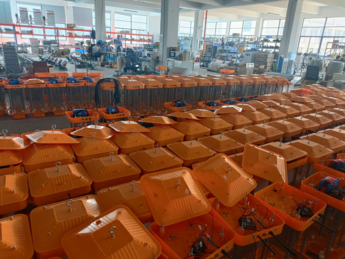
Solar insect trap control should match the target insect's activity period, the available battery energy and the condition of the capture mechanism. A wind-suction trap uses a fan to draw insects into a collection chamber; a frequency-vibration trap uses an electric grid. Both attract insects with light, but their servicing and fault checks differ. For farms evaluating NiuBoL equipment, the useful result is a repeatable capture record alongside crop observations, not simply a full collection container.
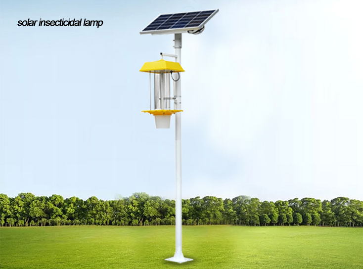
A wind-suction solar insect trap combines an attracting light, fan, collection chamber, controller, battery and solar panel. The light brings responsive flying insects toward the intake. Airflow then carries them into the chamber. Electrical energy still powers the fan: the term wind suction does not mean that ambient wind drives the device.
This arrangement can support an integrated pest management program where the target adult insects respond to the light and occur during the operating period. It cannot be assumed to control insects inside stems, underground stages or every species feeding on a crop. A low catch may reflect limited attraction, poor trap operation or unsuitable weather rather than a low field population. Crop scouting remains necessary.
The distinction matters when comparing equipment. A grid trap and a suction trap can have similar poles and solar panels, yet require different maintenance. For the frequency-vibration solar insect trap, contaminated grid surfaces are an important inspection point. For the suction design, an obstructed intake or poorly seated collection chamber can reduce capture even when the lamp remains illuminated.
The following values describe the NiuBoL wind-suction configuration with a 12.8 V battery. They are component ratings, not a promise of a particular treated area or number of cloudy nights. Match the fan and total-load version when ordering replacements; a lower-power fan package must not be treated as electrically identical to a higher-power package.
| Component | Configuration | Operating implication |
|---|---|---|
| Attracting LEDs | 365 nm and 395 nm bands | Light attraction is species dependent; wavelength alone does not establish crop protection performance. |
| Solar panel | At least 40 Wp | Rated peak power is not the daily energy delivered to the battery. |
| Battery | 12 Ah, 12.8 V LiFePO4 | Nominal stored energy is 153.6 Wh; usable energy is lower after discharge limits and losses. |
| Fan options | 12 V, 20 W or 12 W configuration | Specify the installed version when comparing duty hours or spare fans. |
| Fan speed | 2200 rpm configuration | Rotor speed does not establish airflow through a dirty or blocked intake. |
| Total power versions | Up to 30 W or up to 15 W | Use the matched package rating and measured operating load for battery sizing. |
| Protection | IP65 | Keep joints sealed; the rating does not permit flooding or unrestricted pressure washing. |
| Pole configuration | 3 m galvanized steel pole; 60 mm diameter; 2 mm wall | Foundation and anchoring still depend on soil, exposure and local structural requirements. |
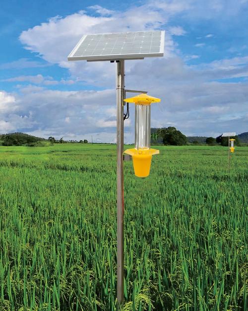
For an illustrative energy check, a continuous 30 W load operating for six hours requires 180 Wh. That exceeds the nominal 153.6 Wh of a 12 Ah, 12.8 V battery before allowing for reserve capacity or conversion losses. A 15 W load over the same period requires 90 Wh. Neither calculation proves actual autonomy, because the operating load, battery condition and available solar charging must also be measured.
Do not multiply panel watts by the number of daylight hours. Estimate charging with local peak-sun-hour data and account for shading, panel temperature, controller losses and seasonal conditions. Where trapping repeatedly stops before the intended end time, inspect charging and battery voltage under load before extending the schedule. A larger panel cannot compensate for a failing battery, and a larger battery will not solve persistent shading.
Solar insect trap control commonly combines light sensing, timed operation and protective shutdown. These functions should have a clear priority: protection may stop the device even when the timer requests operation. During commissioning, check the transition into and out of each operating state, rather than testing only whether the lamp lights after dark.
| Control function | Field check | Interpretation |
|---|---|---|
| Dusk activation | Observe the light sensor during a normal evening with nearby lighting operating. | A floodlight or shaded sensor can change the effective switching time. |
| Timer | Record the actual start, stop and overnight run duration. | A configured period is not evidence that the fan ran throughout it. |
| Humidity protection | Check status during humid weather and subsequent recovery. | A 95%RH protection threshold is not a measurement of rainfall intensity. |
| Low-temperature protection | Check the configured threshold and restart behavior. | A nominal 5 ± 2 °C shutdown setting is an equipment control condition, not a universal insect-activity threshold. |
| Battery protection | Compare voltage at startup and near shutdown under the normal load. | Repeated early stops can indicate inadequate charge, battery deterioration or excessive load. |
Keep the operating clock consistent across a group of traps. If one unit starts an hour earlier, its catch cannot be compared directly with neighboring units without accounting for the different sampling period. Where automatic remote status is unavailable, a short inspection log containing start time, stop time and observed fan operation is more informative than a daily photograph of the container alone.
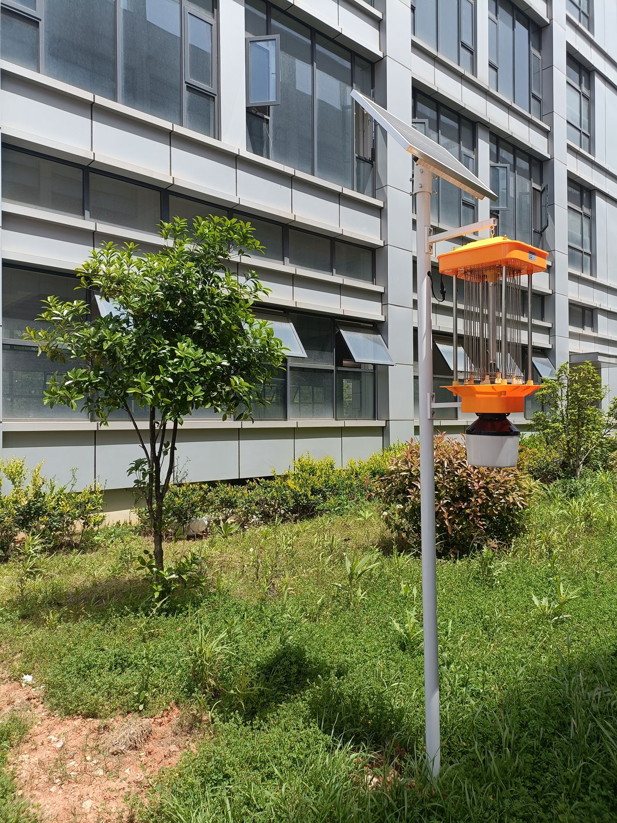
Start with the target species and crop stage. Ask the crop protection team when adults are active locally and what scouting observations would trigger intervention. A fixed first-six-hours-of-night schedule is not automatically suitable for every pest, season or latitude. Nor does that schedule guarantee that beneficial insects avoid the trap.
During a pilot, divide observations into practical time blocks where collection arrangements permit. Record target insects, non-target insects, operating hours and the condition of the crop. Keep placement and inspection methods consistent while testing a timing change. Changing height, lamp schedule and location simultaneously makes it difficult to identify which adjustment affected capture.
For example, an assumed catch of 120 target insects over six operating hours is 20 per trap-hour; 90 over three hours is 30 per trap-hour. This normalization helps describe operating exposure, but it does not prove that the shorter schedule protects the crop better. Catch composition and crop damage must still be compared over a suitable observation period.
Physical trapping does not apply pesticide to the crop during capture. That is different from proving that harvested produce meets a residue limit or that all chemical treatments can be removed. Those decisions require the relevant crop protection program and, where required, residue testing. Likewise, total catch weight is a poor substitute for identifying target and non-target insects.
In an orchard, canopy growth can obstruct attraction and shade the panel later in the season. In a vegetable field, crop rotation can change the relevant pest species. In a research plot, collection consistency may matter more than maximizing catch. Near sensitive habitats, non-target capture can be a reason to reduce operating hours, relocate a trap or discontinue its use after ecological assessment.
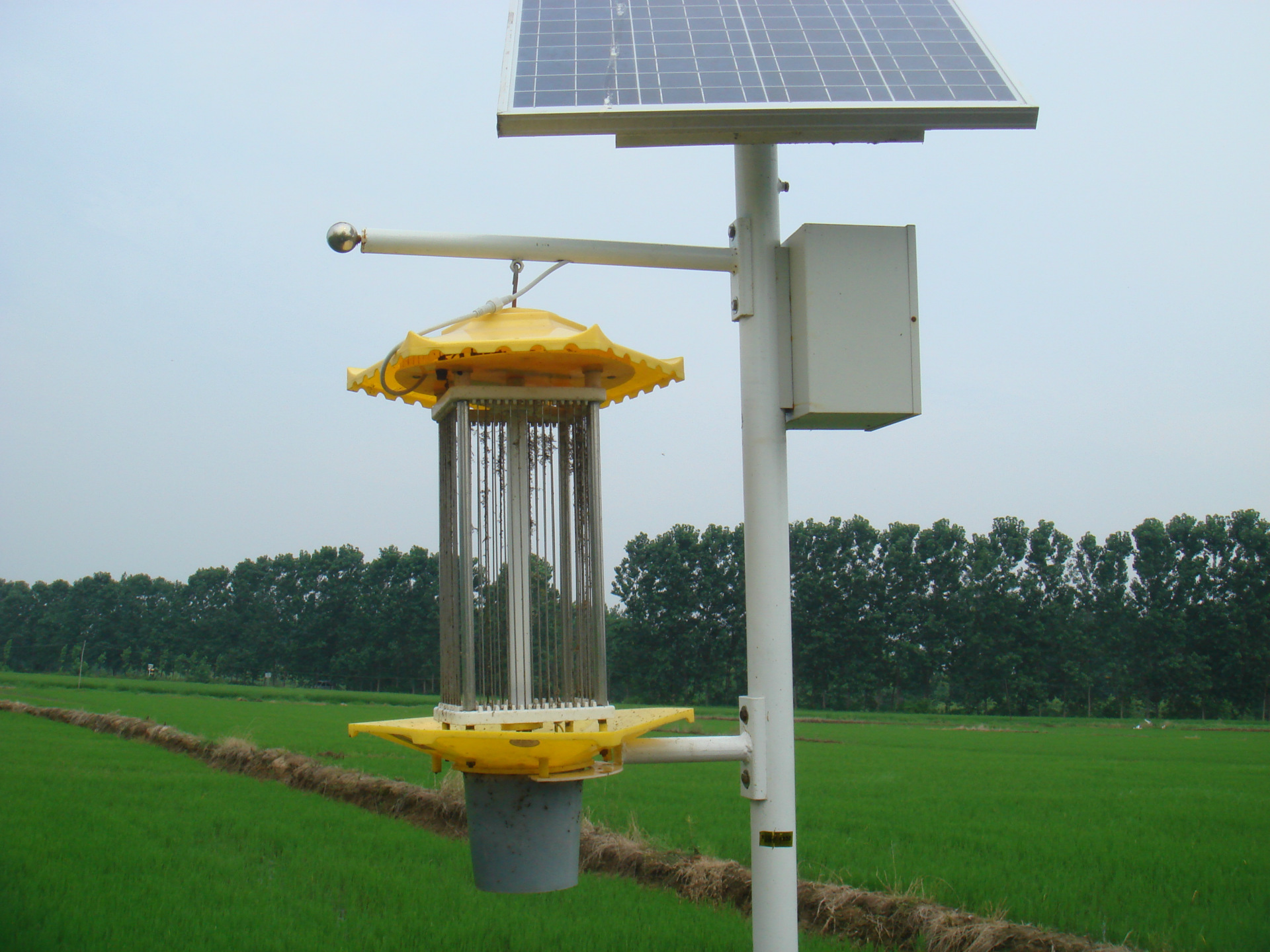
Choose a position accessible for collection and inspection without placing the unit in the path of farm machinery. Avoid competing lights where practical, and check the solar exposure after accounting for the mature crop canopy. Panel direction and tilt should suit the site latitude and hemisphere; a universal south-facing instruction is inappropriate for projects in both hemispheres.
The pole foundation must resist the local wind and ground conditions. A single footing size should not be copied across loose soils, exposed ridges and sheltered plots. Route cables with strain relief and protect connections against irrigation spray and standing water. A tilted pole or loose bracket can affect both mechanical security and the intended collection arrangement.
Before servicing, isolate the energy sources using the equipment's service procedure. A connected solar panel can supply power in daylight even when the battery has been disconnected. Do not reach into a moving fan or an energized grid. For suction equipment, remove collected material, check the intake and outlet for blockage, and reseat the collection chamber. For grid equipment, use its electrical discharge and cleaning procedure instead of applying a fan-cleaning routine.
If the lamp operates but capture drops, first establish whether the target insects are present. Then check airflow, chamber fit, nearby competing light and actual operating hours. A turning fan can still have restricted airflow. If the entire trap stops, inspect controller status, supply connections and the battery before replacing the light source.
A standalone solar trap does not automatically provide RS485, Modbus RTU or remote catch reporting. For a connected project, specify which functions are needed: timed switching, battery voltage, fan fault indication, operating-hour records or image-based insect monitoring. A controller capable of switching a lamp is not necessarily capable of measuring those conditions. Ask NiuBoL to identify the available interface and gateway arrangement for the selected package before designing the farm network.
No universal schedule can guarantee that outcome. Identify the locally active insects and review the non-target catch. Adjusting hours may reduce unwanted capture, but effectiveness must be checked under the actual season and habitat conditions.
Determine deployment through a site plan and pilot observations. Crop canopy, terrain, competing lights and target insect behavior affect attraction. Do not convert an advertised coverage area into a guaranteed control radius or assume neighboring light fields create uniform protection.
The capture cycle must coordinate attraction and suction. A lit lamp with an inactive fan may attract insects without retaining them. Check controller operation and the intended start and stop sequence for the chosen model during commissioning.
No. Inspect accessible connectors, pole stability and the collection path after severe weather. Moisture protection and enclosure sealing do not prevent debris accumulation, a blocked inlet or water entering through an incorrectly assembled joint.
Not by itself. Relate trap observations to crop scouting, pest stage and the intervention criteria used by the responsible crop protection team. Trapping and residue analysis answer different questions and should not be substituted for one another.
Provide the crop, target pests, location, desired nightly operating period, service access and any remote-control requirement. Request a matched list of fan load, battery, panel, controller and collection components so that energy assumptions can be checked before ordering.
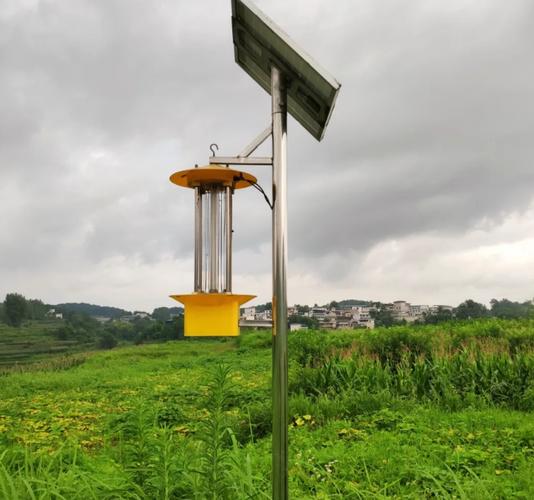
Useful solar insect trap control links operating hours to target insect activity and available electrical energy. Evaluate NiuBoL suction and grid equipment by their actual capture mechanisms, maintenance requirements and field observations. Consistent operating records, non-target assessment and crop scouting provide a sounder basis for deployment than claims of universal coverage or guaranteed pesticide reduction.
Prev:Soil Moisture Monitoring Standards and Applications in Modern Agriculture
Next:Pesticide Residue Rapid Detector: Operation, Controls and Result Limits
Related recommendations
Sensors & Weather Stations Catalog
 Agriculture Sensors and Weather Stations Catalog-NiuBoL.pdf
Weather Stations Catalog-NiuBoL.pdf
Agriculture Sensors Catalog-NiuBoL.pdf
Water Quality Sensor Catalog-NiuBoL.pdf
Related products
 Combined air temperature and relative humidity sensor
 TDR Soil Moisture & Temperature Sensor for irrigation| RS485 |4-20mA| NBL-S-THR
 Soil pH sensor RS485 soil Testing instrument soil ph meter for agriculture |NBL-S-PH
 Wind Speed sensor Output Modbus/RS485/Analog/0-5V/4-20mA
 Tipping bucket rain gauge for weather monitoring auto rainfall sensor RS485/Outdoor/stainless steel
 Pyranometer Solar Radiation Sensor 4-20mA/RS485


Screenshot, WhatsApp to identify the QR code
WhatsApp number:+8615367865107
(Click on WhatsApp to copy and add friends)

