





— Blogs —
—Products—
 Consumer hotline +8618073152920
WhatsApp:+8615367865107
Address:Room 102, District D, Houhu Industrial Park, Yuelu District, Changsha City, Hunan Province, China
Product knowledge
Time:2024-03-02 20:49:37 Popularity:9158
Where should a weather station be located? A weather station should be installed at a location that provides representative atmospheric measurements while minimizing interference from buildings, trees, artificial heat sources, obstacles and unsuitable ground surfaces.
For conventional outdoor meteorological monitoring, an open area with suitable exposure and relatively uniform surrounding terrain is generally preferred. However, the ideal installation depends on the purpose of the observations and the instruments being used.
Different weather sensors have different siting requirements. Air temperature and relative humidity sensors are commonly installed approximately 1.25–2.0 meters above representative ground, while a standard reference height for surface wind measurements is 10 meters. Rain gauges and pyranometers require their own mounting arrangements.
The following guide explains weather station placement, recommended measurement heights, obstacle clearance, ground conditions and installation considerations for agricultural, environmental and meteorological monitoring.
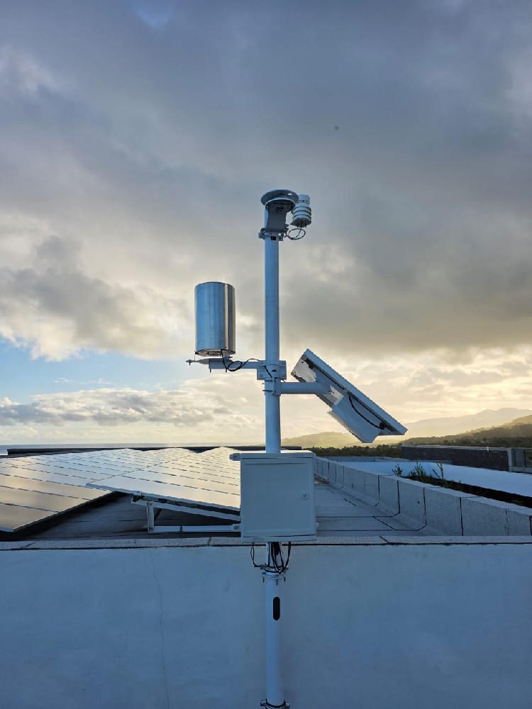
Weather station installation heights should be selected according to the measured parameter. A single mounting height is not suitable for every meteorological sensor.
| Instrument | Typical Height / Position | Main Siting Requirement |
|---|---|---|
| Air Temperature Sensor | 1.25–2.0 m above ground for standard surface observations | Ventilated radiation shield; representative ground surface; away from artificial heat |
| Relative Humidity Sensor | Commonly colocated with air temperature | Suitable ventilation and representative atmospheric exposure |
| Wind Speed / Direction Sensor | 10 m is a common standard reference height | Open airflow; minimize building and tree interference |
| Rain Gauge | Network-specific; often around 1 m above ground | Level catchment opening; suitable wind exposure; avoid splash and obstruction |
| Pyranometer | Appropriate unobstructed mounting position | Correct sensing-plane orientation; avoid shading and unwanted reflections |
| Soil Temperature Sensor | Selected depth below ground | Representative soil layer and suitable thermal contact |
| Soil Moisture Sensor | Crop root-zone or project-specific depth | Representative soil conditions and good probe contact |
These heights are general references rather than universal requirements for every station. Formal meteorological networks may specify more detailed exposure classes, mounting heights, measurement uncertainties and observation procedures.
For agricultural microclimate research, greenhouse monitoring or specialized industrial installations, different measurement heights may be appropriate. The selected height should be documented so that observations can be interpreted correctly.
Nearby buildings, trees, walls and other structures can affect weather observations by altering airflow, blocking radiation, changing local temperatures or influencing precipitation catch.
For a weather station intended to represent conditions over a broader area, an open site away from major obstructions is generally preferred.
However, the required clearance depends on the instrument. Wind sensors are particularly sensitive to airflow obstruction, while air temperature sensors are also affected by shading, nearby surfaces and artificial heat sources.
For standard wind measurements, a commonly used siting guideline is to maintain a horizontal distance from major obstructions of approximately ten times the obstruction height, where practical.
For example, if a building is 5 meters high, a distance of approximately 50 meters may be considered as a wind-exposure guideline.
This is a practical guideline, not a guarantee of unobstructed measurements. Actual airflow effects also depend on building geometry, sensor height, wind direction, terrain and surrounding roughness.
Rain gauges and temperature sensors use different exposure criteria. Applying the same obstacle clearance rule to every weather station instrument is not appropriate.

For conventional near-surface meteorological observations, air temperature and relative humidity sensors are commonly installed between 1.25 and 2.0 meters above ground level.
This height range is used to support comparable measurements of the near-surface atmosphere under specified exposure conditions.
The sensor should be installed in a suitable radiation shield that protects the sensing element from direct solar heating while allowing representative air exchange.
Direct sunlight can heat an exposed temperature sensor above the actual temperature of the surrounding air.
A ventilated radiation shield helps reduce unwanted radiation effects. Depending on the application, the shield may use natural ventilation or an appropriate forced-air arrangement.
The shield itself should be installed away from surfaces and structures that may produce unrepresentative heating or cooling.
Air temperature and humidity sensors should not be installed immediately beside air-conditioning outlets, exhaust vents, heating equipment, generators or similar sources of localized heat.
Nearby irrigated surfaces, water features and humidifiers can also influence relative humidity readings.
The measurement location should represent the intended air environment rather than the conditions created by a nearby device or surface.
Wind speed and direction measurements are strongly influenced by the installation height and surrounding terrain.
Buildings, trees and roof edges can block, accelerate or redirect airflow. These effects may cause measured wind speed and direction to differ from the conditions at an unobstructed reference location.
A height of 10 meters above ground level is a widely used reference for standard surface wind observations.
Using a defined measurement height improves comparability between stations, provided the surrounding exposure conditions are also suitable.
However, not every agricultural or industrial wind measurement requires a 10-meter mast.
For example, an agricultural project may intentionally measure wind near crop height, while an industrial site may monitor wind at a height relevant to equipment operation. These observations serve different purposes from standard 10-meter meteorological measurements.
A rooftop wind sensor may be affected by turbulence and airflow acceleration around the building.
When a roof installation is unavoidable, the sensor should be positioned to reduce interference from the roof and nearby structures as much as practical.
Where possible, a dedicated mast in open terrain provides a more representative arrangement for conventional meteorological wind monitoring.
The wind direction sensor should be aligned to its specified directional reference during installation. For data reporting, the distinction between geographic north and any installation reference should be handled correctly.
A rain gauge requires a suitable collection position that allows precipitation to reach its measurement opening without unnecessary obstruction.
The catchment opening should be level, and the instrument should be installed according to its mounting and exposure requirements.
Rain gauge installation height depends on the observation network, local environmental conditions and instrument design.
A height near 1 meter is used in some meteorological observation practices, while other standards and networks specify different heights.
The collection opening should be positioned to reduce rain splash from nearby surfaces and avoid blockage by vegetation or snow accumulation.
Trees and buildings can affect the amount of precipitation reaching the rain gauge.
Wind can also alter the flow of precipitation around the collection opening. In highly exposed locations, suitable wind shielding may improve precipitation catch for certain measurement arrangements.
As a practical siting reference, some observation guidance recommends a distance from significant obstructions of approximately four times their height for rain gauges. The applicable standard and site conditions should determine the final installation.
For a tipping bucket rain gauge, the instrument should also be mounted securely, leveled and accessible for cleaning the funnel and inspecting the mechanism.

A pyranometer measures solar irradiance incident on its receiving plane.
For Global Horizontal Irradiance (GHI), the pyranometer should be mounted horizontally with an unobstructed view of the sky, following the instrument's leveling and installation instructions.
Nearby trees, buildings, antenna structures and mounting poles can create shadows that affect the measured solar irradiance.
The installation should minimize unwanted shadows over the measurement period.
Nearby reflective surfaces may also influence some measurements. Suitable sensor positioning should consider the intended field of view and receiving plane.
For GHI measurement, the sensing plane is horizontal.
For photovoltaic Plane-of-Array (POA) irradiance monitoring, the instrument is installed parallel to the photovoltaic module plane.
The two arrangements measure irradiance on different planes and should not be confused.
There is no universal pyranometer mounting height that is equivalent to the standard 10-meter reference for wind measurements. The important considerations are orientation, exposure, maintenance accessibility and instrument requirements.
The surface surrounding a weather station can strongly influence near-ground air temperature, humidity and other meteorological measurements.
For conventional agricultural and general-purpose surface weather observations, relatively uniform natural ground cover is often preferred.
Concrete, asphalt, dark roofs and other artificial surfaces can absorb and release heat differently from surrounding vegetation or natural soil.
A temperature sensor installed near a large paved area may therefore measure a local thermal environment that differs from conditions over nearby agricultural land.
Deep depressions, steep slopes, narrow valleys and unusually exposed hilltops may have local temperature or wind conditions that differ from the surrounding area.
These locations are not necessarily unsuitable for every monitoring project. They may be appropriate when the purpose is to study a particular local microclimate.
For general weather observation, however, the site should represent the area for which the measurements will be used.
Different monitoring applications may require different installation locations, measurement heights and instrument configurations.
| Application | Main Siting Consideration |
|---|---|
| Agricultural Weather Station | Representative crop environment, suitable ground cover and sensor exposure. |
| Greenhouse Monitoring | Representative internal climate, crop-canopy position and separation from localized heating or ventilation. |
| Solar PV Weather Station | Unshaded irradiance measurements and suitable module-plane alignment for POA observations. |
| Hydrological Monitoring | Representative precipitation exposure, site accessibility and compatibility with other hydrological measurements. |
| Urban Weather Monitoring | Site selection according to the intended urban environment and clearly documented local influences. |
| Reference Meteorological Observation | Specified measurement heights, exposure criteria, calibration and complete site documentation. |
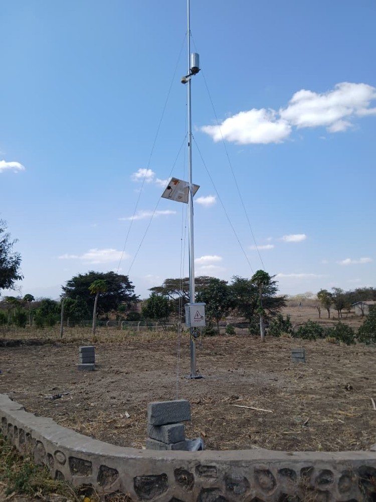
Agricultural stations are often installed within or near the fields they monitor, at locations representative of the crops and local growing conditions.
For irrigation planning, it is important to avoid placing sensors where unusual wetting, heating or airflow conditions may bias measurements.
Some agricultural systems also use soil moisture, soil temperature, leaf wetness or PAR sensors. Their installation conditions are different from those of standard atmospheric sensors.
An urban weather station may be intentionally installed to observe local conditions influenced by buildings, roads and urban land cover.
For urban climate research, avoiding all built structures is not always the objective. Instead, the monitoring location should represent the urban conditions being studied.
The surrounding building geometry, surface materials and sensor height should be documented for correct interpretation.
Compact multi-parameter weather sensors simplify installation by combining several measurements into one instrument.
For example, an integrated ultrasonic weather sensor may measure wind speed, wind direction, air temperature, humidity and atmospheric pressure.
However, combining these measurements in one housing can create an installation compromise because standard wind and air temperature observations often use different mounting heights.
A compact sensor installed near 2 meters above ground may provide useful local weather measurements, but its wind readings should not automatically be treated as equivalent to measurements from a standard 10-meter wind installation.
Similarly, placing an integrated weather sensor at 10 meters may not provide the preferred exposure or maintenance accessibility for all its other measurement functions.
The installation should therefore be selected according to the main monitoring objective, with any nonstandard measurement heights documented.
For projects that require independently positioned measurements, a modular automatic weather station with separate sensors may be more appropriate.
A weather station installation must also consider power supply, communication equipment, structural stability and maintenance requirements.
Remote stations may use a solar panel, charge controller and rechargeable battery. The power system must be sized for the actual sensor and gateway consumption, local solar conditions and required backup duration.
For remote data transmission, the site must have suitable network connectivity through a supported cellular, Ethernet, Wi-Fi or other communication arrangement.
A good meteorological location is not automatically a good radio or cellular communication location. Antenna placement may need to be considered separately from the measurement sensors.
The mounting pole or mast should provide adequate structural strength for the equipment and expected environmental loading. Appropriate grounding, electrical protection and safe maintenance access should be included in the installation plan.
Rain gauges require periodic cleaning, pyranometers require suitable optical surface maintenance, and exposed equipment may need inspections after severe weather.
Accurate weather data interpretation depends not only on the measurements but also on knowing how and where the instruments were installed.
For long-term monitoring projects, record the station's installation information and important environmental characteristics.
| Site Information | What to Record |
|---|---|
| Station Location | Coordinates, elevation and site identification. |
| Sensor Height | Height above ground or depth below ground for each instrument. |
| Ground Cover | Grass, bare soil, pavement, roof or other surrounding surface. |
| Nearby Obstacles | Buildings, trees, fences, their approximate heights and distances. |
| Sensor Configuration | Models, measurement parameters, shielding and orientation. |
| Installation Records | Installation date, site photographs, maintenance and significant changes. |
Site photographs showing the surrounding landscape can be more useful for assessing instrument exposure than close-up photographs of the sensors alone.
If trees grow, new buildings are constructed or land use changes, the station's exposure may also change over time. Such changes should be documented when analyzing long-term weather records.
Mounting every sensor at one height: Different instruments have different reference heights and exposure requirements. An integrated station may require a documented compromise.
Installing temperature sensors in direct sunlight: Without suitable radiation shielding, the sensing element may become warmer than the surrounding air.
Placing wind sensors near walls or roof edges: Buildings can distort wind speed and direction measurements through turbulence, acceleration and shielding.
Installing rain gauges beneath trees: Branches can intercept precipitation and introduce debris into the collection funnel.
Allowing pyranometer shading: Shadows from poles, trees or buildings can cause solar irradiance measurements to be unrepresentative of the intended plane.
Ignoring ground-surface effects: Concrete, asphalt and other artificial surfaces can change local thermal conditions relative to natural ground.
Failing to document the site: Missing height, exposure or equipment information makes long-term comparisons and interpretation more difficult.

A1. A general-purpose weather station should be installed at a representative location with suitable ground cover and exposure, away from major obstructions and artificial heat or moisture sources. The final site depends on the observation objectives.
A2. There is no single correct height for the entire station. Standard air temperature and humidity observations commonly use 1.25–2.0 meters, while a common reference height for wind measurements is 10 meters. Other sensors have their own requirements.
A3. The distance depends on the measurement. For wind exposure, a commonly used guideline is approximately ten times the height of a significant obstruction. Rainfall, temperature and solar radiation measurements use different siting considerations.
A4. Yes, for suitable monitoring objectives. However, roof surfaces and building airflow can influence temperature, humidity and wind readings. Rooftop measurements should not automatically be considered equivalent to standard open-field observations.
A5. A rain gauge should be installed at a suitable, level location with an unobstructed collection opening, appropriate wind exposure and sufficient clearance from splash and surrounding obstacles. The height should follow the applicable observation method.
A6. No. A pyranometer's installation is determined primarily by its measurement plane, sky exposure, shading and instrument requirements. The 10-meter reference height is associated with standard wind measurements, not a universal pyranometer requirement.
A7. Not necessarily. Integrated sensors combine several measurements in one housing, while different meteorological parameters may have different preferred observation heights. The installation should reflect the intended purpose and document any compromises.
A8. Different surfaces absorb, reflect and release heat differently. Grass, bare soil, pavement and roofs can create different local temperature and humidity conditions, influencing the representativeness of the measurements.

NiuBoL provides weather station sensors and configurable automatic weather monitoring equipment for agriculture, meteorology, environmental observation and hydrological monitoring.
For complete monitoring configurations, see the Automatic Weather Station product selection page.
For a detailed explanation of sensors, data logging and communication, see How Does a Weather Station Work?
For weather station installation planning, specify the monitoring purpose, sensor parameters, proposed site, nearby obstructions, mounting requirements, power supply, data acquisition interface and communication needs.
For formal meteorological observations, the applicable observation network and instrument-specific siting requirements should take precedence over general installation guidelines.
Related recommendations
Sensors & Weather Stations Catalog
 Agriculture Sensors and Weather Stations Catalog-NiuBoL.pdf
Weather Stations Catalog-NiuBoL.pdf
Agriculture Sensors Catalog-NiuBoL.pdf
Water Quality Sensor Catalog-NiuBoL.pdf
Related products
 Combined air temperature and relative humidity sensor
 TDR Soil Moisture & Temperature Sensor for irrigation| RS485 |4-20mA| NBL-S-THR
 Soil pH sensor RS485 soil Testing instrument soil ph meter for agriculture |NBL-S-PH
 Wind Speed sensor Output Modbus/RS485/Analog/0-5V/4-20mA
 Tipping bucket rain gauge for weather monitoring auto rainfall sensor RS485/Outdoor/stainless steel
 Pyranometer Solar Radiation Sensor 4-20mA/RS485


Screenshot, WhatsApp to identify the QR code
WhatsApp number:+8615367865107
(Click on WhatsApp to copy and add friends)

