





— Blogs —
—Products—
 Consumer hotline +8618073152920
WhatsApp:+8615367865107
Address:Room 102, District D, Houhu Industrial Park, Yuelu District, Changsha City, Hunan Province, China
Product knowledge
Time:2025-11-04 12:00:12 Popularity:1060
A farm weather station network can use local links to a central gateway or independent onward connections at separate sites. The choice depends on actual coverage, site power, failure impact and service access. Neither a fixed wireless range nor the word smart establishes a suitable network. Review the field layout and supported equipment before duplicating a station design across the farm.
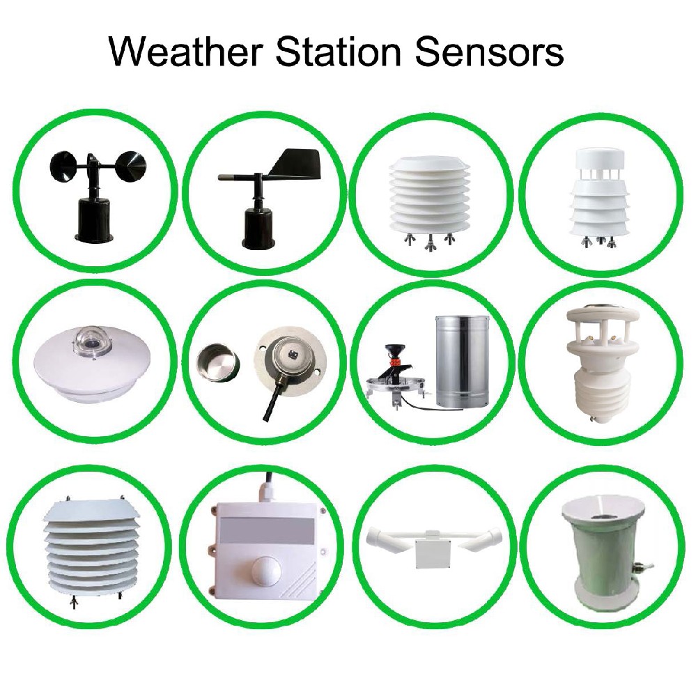
Mark the observations that need separate locations: weather reference points, crop blocks, greenhouse zones or other selected instruments. Record where power and a practical onward connection are available. Nearby points may share acquisition equipment; distant or obstructed points may need a different arrangement.
Separate sensor wiring from the onward link. A weather head with RS485 Modbus RTU still needs compatible acquisition, whether the collected observations later travel through a local radio link or cellular service. A wireless station is not necessarily a wire-free instrument installation.
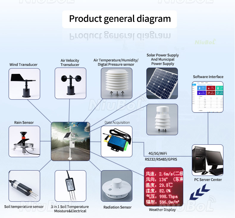
| Question | Central gateway arrangement | Independent onward sites |
|---|---|---|
| Collection route | Several field points send data through one supported local network | Each selected station has its own onward connection |
| Common failure | A gateway or shared uplink interruption can affect several points | One station's link can fail without stopping another independent link |
| Coverage work | Verify each field-to-gateway path and the gateway's onward route | Verify onward coverage at every proposed site |
| Power and service | Field devices and central equipment both require support | More separate communication equipment may need power and service |
| Recurring charges | Depend on shared network and receiving-service scope | Depend on individual connections and services |
| Expansion | Check gateway and local-network capacity | Check each added site's equipment and receiving identity |
These are architecture alternatives, not confirmation that every product supports both. For a central network, identify the actual field radios and gateway. For independent cellular stations, identify the modem or logger configuration for the destination.
One collection point can simplify some service work, but it also concentrates responsibility. If its onward connection stops, several sites may disappear from the remote view at once. Specify whether field points continue recording and how those records can be retrieved.
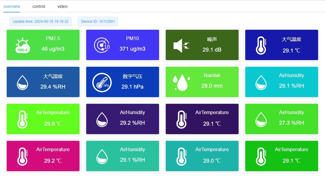
Do not equate local radio contact with complete delivery to the customer's server. Test the field path and the onward route separately. A data display can remain visible even when one observation point has stopped updating, so retain distinct station identities and observation times.
The NBL-PH-1 4G data logger is one option for compatible acquisition and cellular transfer. Check destination bands, SIM/APN and server requirements at each site. Do not use coverage at the farm office as evidence for a remote field or sheltered position.
| NBL-PH-1 function | Capability | Network planning check |
|---|---|---|
| Field acquisition | RS485 and RS232; configured compatible inputs | Selected instruments and input allocation |
| Local history | FLASH; saving interval 1-240 minutes | Needed record period and retrieval method |
| Onward link | Configured 4G transfer | Local service and receiving-system compatibility |
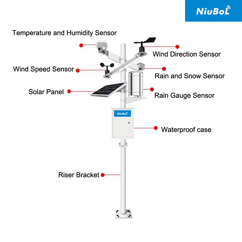
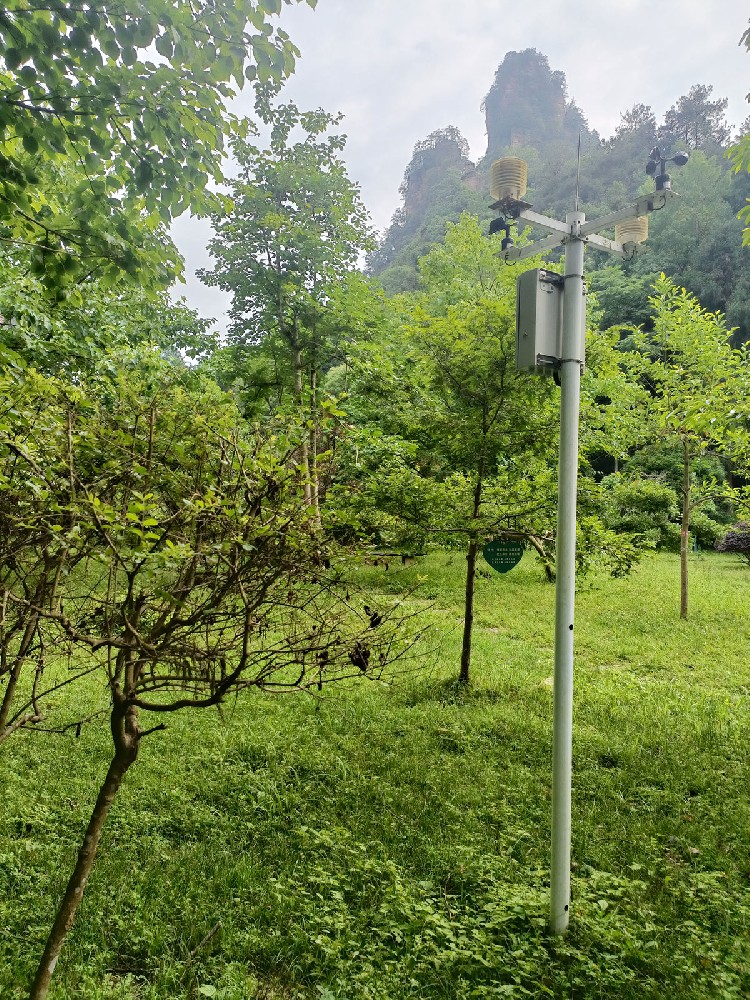
Inspect the intended antenna position, nearby terrain, buildings and vegetation. Seasonal crop growth can change the surroundings. A temporary test made above a vehicle or outside the proposed enclosure may not represent the permanent installation.
For any selected local radio technology, verify its actual topology, configuration and regional requirements. A generic 2-5 km claim does not establish a working path through vegetation or behind terrain. Include antennas, mounting and any necessary intermediate equipment in the quotation rather than assuming them from the radio name.
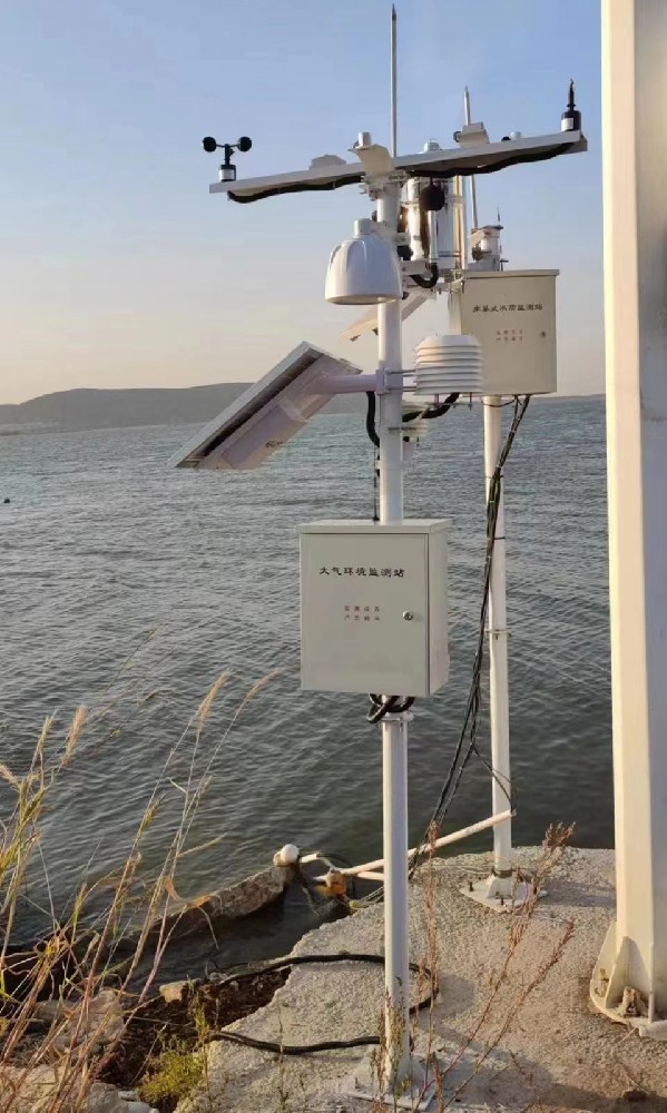
Count the loads at each field site and at any central equipment location. More frequent transfer or another radio can change the supply requirements. A solar assembly suitable for a sensor-only point may not support a combined collector, onward modem and display.
Keep each site's service route visible on the plan. A central design may reduce the number of onward connections while still requiring visits to distributed batteries or instruments. An independent design may isolate some failures but increase the number of separate communication units to maintain.
Prove the proposed route with representative records at the intended position before ordering identical equipment for many points. Test the required interruption behavior without assuming automatic backfill. Then add sites with unique identities and confirm that the receiving system keeps their records separate.
Send NiuBoL a location map, the required measurements, available power and the intended receiver. Ask for the supported equipment and connection scope for each path. Compare initial and recurring costs using the same site count; there is no universal lower-cost architecture for every farm.
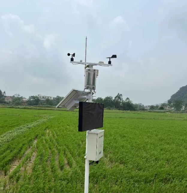
No. Include local radios, power, antennas, coverage work and the effect of a shared outage. Compare the complete scope with independent connections at the same locations.
No. The field-to-gateway path must work, and remote access still needs an appropriate onward route. Local radio coverage and internet availability are separate checks.
Only when electrical, protocol and acquisition functions match. Verify addresses, register definitions and supported input types for the actual gateway and sensors.
No. Demonstrate the delivered retrieval and transfer behavior. Keep observation times with recovered records rather than treating their arrival as a new measurement.
A site map, identified equipment on each link, power at every location, required record intervals and the receiving destination. Include who supplies network services and who maintains each field point.
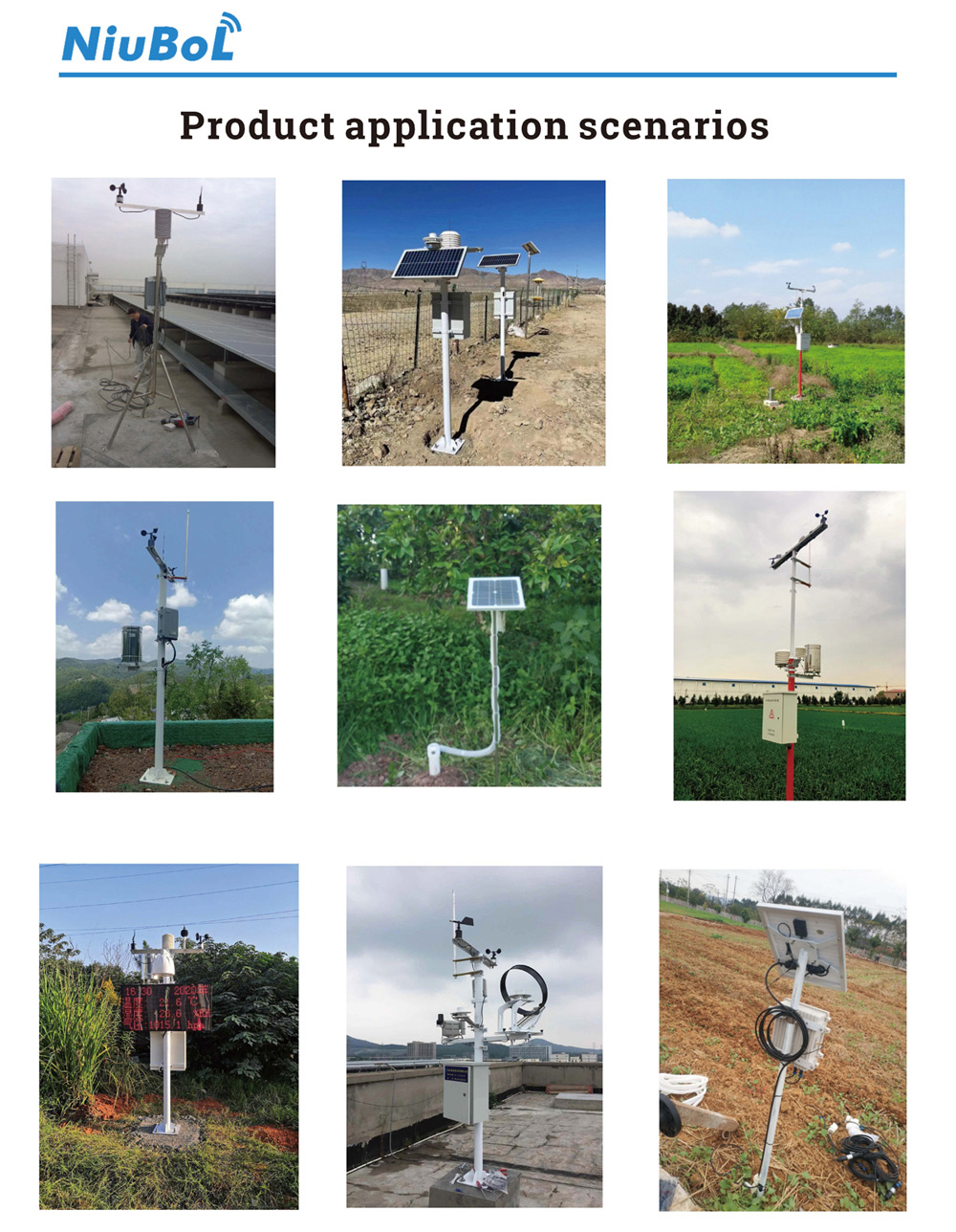
A farm weather station network should be selected by tested routes and explicit failure responsibilities. Compare a central gateway with independent onward sites using coverage, power and service requirements. Start with a demonstrated connection, then expand without relying on fixed range or platform promises.
Prev:Best Wireless Soil Moisture Sensors for Precision Irrigation
Next:Buy Weather Station Online — Complete Guide for Professional Users
Related recommendations
Sensors & Weather Stations Catalog
 Agriculture Sensors and Weather Stations Catalog-NiuBoL.pdf
Weather Stations Catalog-NiuBoL.pdf
Agriculture Sensors Catalog-NiuBoL.pdf
Water Quality Sensor Catalog-NiuBoL.pdf
Related products
 Combined air temperature and relative humidity sensor
 TDR Soil Moisture & Temperature Sensor for irrigation| RS485 |4-20mA| NBL-S-THR
 Soil pH sensor RS485 soil Testing instrument soil ph meter for agriculture |NBL-S-PH
 Wind Speed sensor Output Modbus/RS485/Analog/0-5V/4-20mA
 Tipping bucket rain gauge for weather monitoring auto rainfall sensor RS485/Outdoor/stainless steel
 Pyranometer Solar Radiation Sensor 4-20mA/RS485


Screenshot, WhatsApp to identify the QR code
WhatsApp number:+8615367865107
(Click on WhatsApp to copy and add friends)

