

— Blogs —
—Products—
 Consumer hotline +8618073152920
WhatsApp:+8615367865107
Address:Room 102, District D, Houhu Industrial Park, Yuelu District, Changsha City, Hunan Province, China
Product knowledge
Time:2025-10-29 17:50:35 Popularity:919
Liquid flow meter accuracy must be compared at the flow rates the process actually uses. A percentage of reading and the same percentage of full scale produce different error limits, particularly at low flow. Check the meter's calibrated range, liquid properties and installation conditions before treating a headline accuracy figure as an installed-system guarantee.
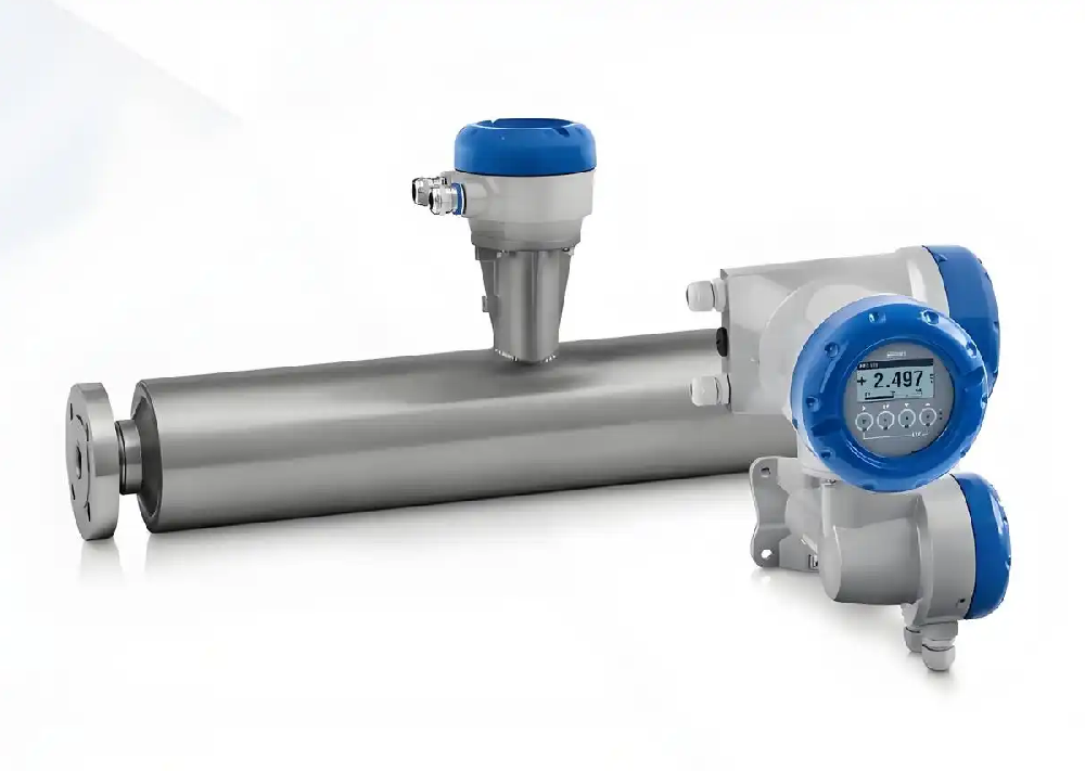
A dosing line may spend most of its time far below the meter's maximum range. Selecting a meter only by pipe diameter and its smallest advertised error can leave that operating point poorly characterized. Obtain minimum, normal and maximum flow, plus startup or batch conditions, before comparing offers.
Consider an illustrative 0-100 L/min range at a working flow of 10 L/min. An error limit of ±0.5% of reading gives ±0.05 L/min at that point. An error limit of ±0.5% of full scale gives ±0.5 L/min, or 5% of the working flow. These are arithmetic examples, not specifications for the illustrated instruments.
| Illustrative error statement | At 10 L/min on a 100 L/min full scale | Purchasing implication |
|---|---|---|
| ±0.5% of reading | ±0.05 L/min | Check whether a low-flow cutoff or additional absolute term applies |
| ±0.5% of full scale | ±0.5 L/min | Evaluate the larger relative error at low operating flow |
| Percentage plus a fixed term | Cannot be evaluated without both terms | Retain the complete expression and its units |
| Calibration uncertainty | Belongs to a particular calibration result and conditions | Do not substitute it for an unrelated installed error limit |
A mass-flow requirement and a volume-flow requirement are not identical. Converting between them needs the appropriate density for the liquid and conditions. A Coriolis instrument measures mass flow using vibrating tubes; electromagnetic and turbine instruments are commonly used for volumetric measurement. The chosen model and application determine suitability, not the name of the principle alone.
For a blending process ordered by mass, a volume reading combined with an assumed fixed density can introduce another source of error. For a water balance, make sure all compared totals use compatible units and time periods. An accurate instantaneous indication does not automatically establish an accurate batch total.
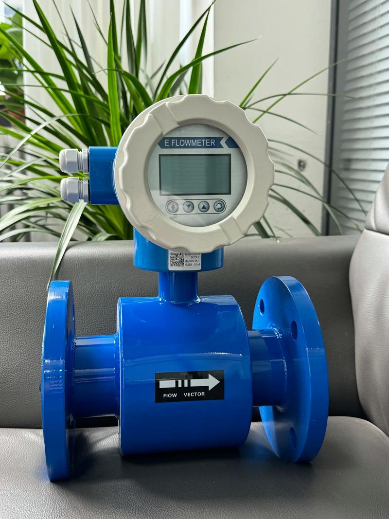
An electromagnetic meter requires a suitably conductive liquid. Electrode and lining compatibility remain important for corrosive or abrasive service. A full-pipe installation must maintain the required filled condition; entrained gas or a partially filled measuring section can invalidate the intended measurement arrangement.
A turbine meter uses a moving rotor and requires attention to liquid cleanliness, viscosity and mechanical condition. Do not apply a clean-water calibration to a significantly different liquid without reviewing its applicability. Coriolis meters also have application limits: gas entrainment, vibration, pressure drop and the selected size can matter even though the measurement principle is different.
NIST's liquid-flow calibration guidance limits calibration results to the calibrated range and discusses additional uncertainty associated with viscosity. For a buyer, the useful question is whether the quoted performance covers the intended liquid and operating conditions, rather than whether one technology always has a lower error.
Describe nearby elbows, reducers, pumps and control valves in the enquiry. Straight-run requirements depend on the meter design and flow disturbances; a single upstream/downstream rule should not be applied to every technology. Obtain the installation requirements for the selected instrument before approving a short spool piece.
For a full-pipe meter, choose a position that avoids persistent gas pockets and loss of fill under the expected operating sequence. For a vibrating-tube instrument, review supports and external vibration. Follow the selected model's orientation requirements rather than prescribing horizontal installation for every Coriolis assembly.
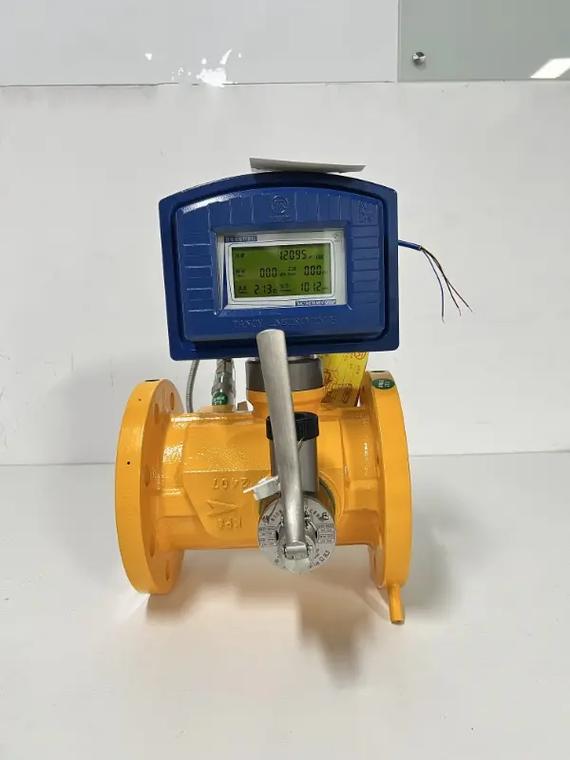
If the receiving PLC counts pulses, confirm the meter factor, pulse width and input frequency capacity. For example, a hypothetical factor of 100 pulses/L makes 2,500 valid pulses equal 25 L. A factor interpreted as L/pulse instead would produce a very different result. This example explains conversion, not an output specification for a pictured meter.
For analog acquisition, check the signal's configured endpoints and the receiving input's contribution to error. For RS485 Modbus RTU versions, obtain the actual register map, scaling, units and totalizer behavior. The presence of RS485 terminals does not establish identical data formats or remote connectivity.
Run a comparison over a defined time or collected quantity with an appropriate reference. Include representative low and normal flows, not only a convenient high-flow point. Record liquid conditions and whether pumps or valves cycled during the run. A calibration document should identify the instrument and conditions relevant to the proposed use.
NiuBoL's non-contact radar flowmeter is a different arrangement for suitable open-water sections. It combines surface-velocity and level observations with section information. It is not a replacement for a Coriolis or other inline meter in a closed pressurized chemical line. Identify whether the task is pipe flow or open-channel discharge before requesting equipment.
For a project review, provide the liquid, normal and minimum flow, required quantity, pipe or channel geometry and existing acquisition equipment. Where a specific inline model is proposed, request its individual performance and material documentation rather than relying on a general technology comparison.
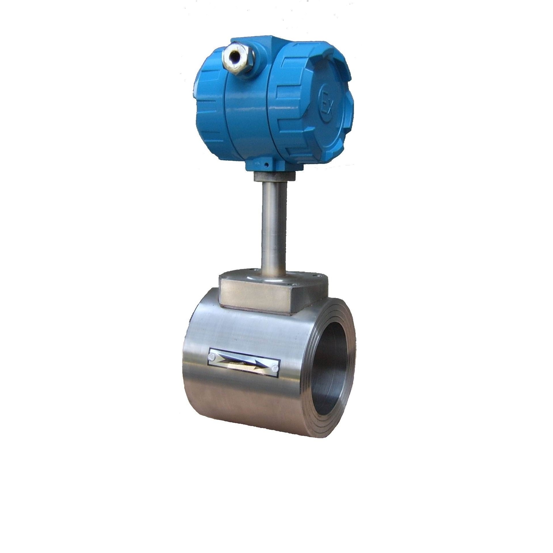
Only comparable error expressions can be ranked that way. Check reading versus full-scale basis, additional terms, valid flow range and test conditions before comparing the percentages.
Only if that flow lies within its qualified operating range and meets the required uncertainty and response. Matching the process pipe diameter does not establish acceptable low-flow measurement.
No. Review the calibrated fluid, range and conditions, then assess differences in the intended application. Viscosity, temperature or two-phase behavior may require further evaluation.
No universal straight-run pair applies to every meter and disturbance. Use the selected design's installation requirements and consider the actual upstream fittings and operating flow path.
Provide the complete error statement, minimum and normal operating flows, liquid properties, installation layout and reference method. Include how the PLC receives rate and total values so acquisition errors can be checked as well.
Evaluate liquid flow meter accuracy across the real operating range, using the full error expression and relevant liquid conditions. Then check installation and acquisition. A technology label or a single calibration point cannot replace that application-specific comparison.
Prev:How to Choose the Right Water Flow Meter
Next:Ultrasonic Integrated Weather Station Specifications: Compare Exact Models
Related recommendations
Sensors & Weather Stations Catalog
 Agriculture Sensors and Weather Stations Catalog-NiuBoL.pdf
Weather Stations Catalog-NiuBoL.pdf
Agriculture Sensors Catalog-NiuBoL.pdf
Water Quality Sensor Catalog-NiuBoL.pdf
Related products
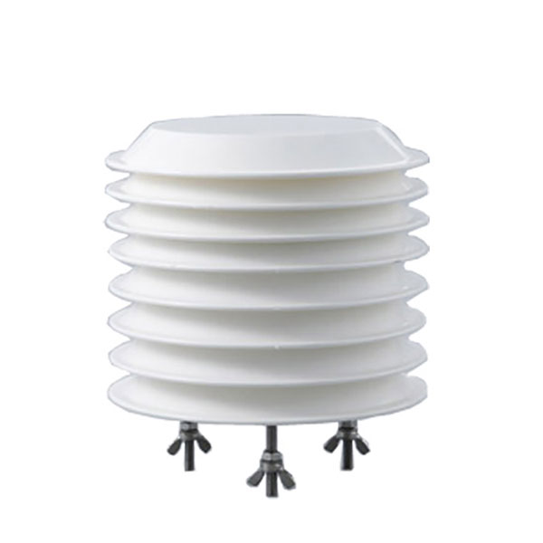 Combined air temperature and relative humidity sensor
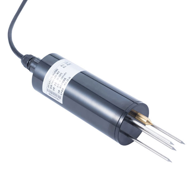 TDR Soil Moisture & Temperature Sensor for irrigation| RS485 |4-20mA| NBL-S-THR
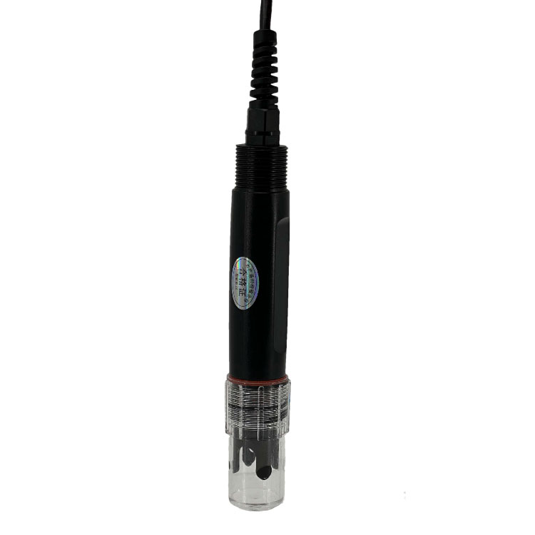 Soil pH sensor RS485 soil Testing instrument soil ph meter for agriculture |NBL-S-PH
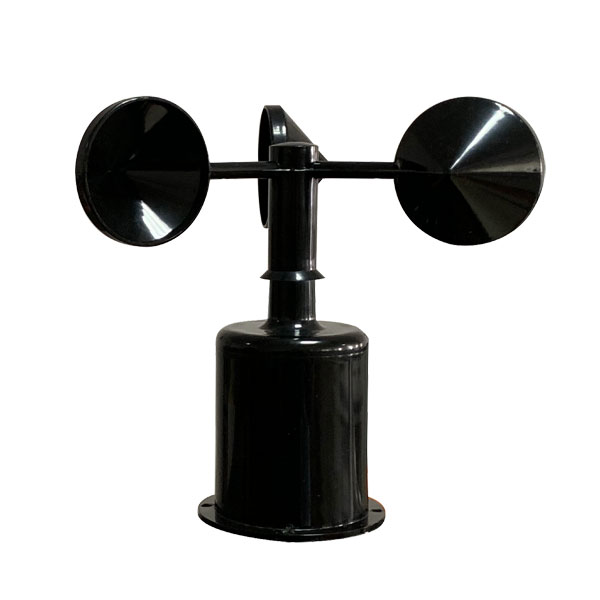 Wind Speed sensor Output Modbus/RS485/Analog/0-5V/4-20mA
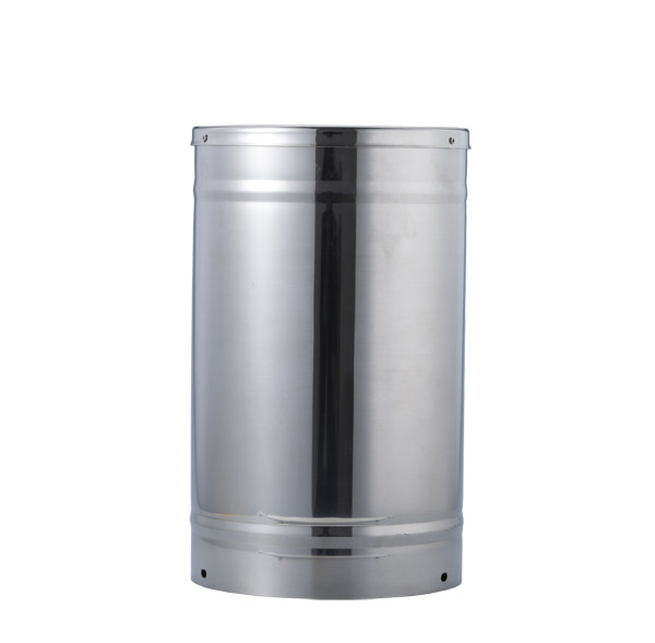 Tipping bucket rain gauge for weather monitoring auto rainfall sensor RS485/Outdoor/stainless steel
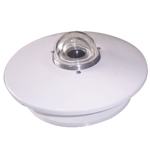 Pyranometer Solar Radiation Sensor 4-20mA/RS485


Screenshot, WhatsApp to identify the QR code
WhatsApp number:+8615367865107
(Click on WhatsApp to copy and add friends)