





— Blogs —
—Products—
 Consumer hotline +8618073152920
WhatsApp:+8615367865107
Address:Room 102, District D, Houhu Industrial Park, Yuelu District, Changsha City, Hunan Province, China
Product knowledge
Time:2025-10-29 17:40:33 Popularity:1083
Quick Answer: Choose a water flow meter by first identifying whether water fills a closed pipe, moves through a partially filled conduit, or flows in an open channel. Then match the measurement principle to water properties, the smallest operating flow and the available installation. Pipe diameter alone is not enough. A water level sensor measures depth or distance; it only supports a flow calculation when a suitable hydraulic relationship or a separate velocity measurement is available.
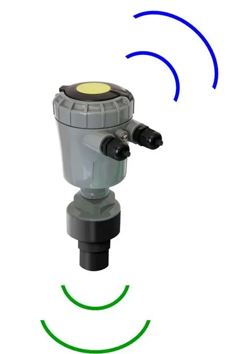
A full irrigation main, a gravity drain and a river section need different measurement arrangements. In a full pipe, the internal cross-sectional area is fixed. In a partially filled pipe or channel, the wetted area changes with depth. Choosing a meter for the wrong condition can produce a believable display without a valid flow measurement.
Establish what the project needs to know. Instantaneous flow supports pump adjustment or an alarm. Accumulated volume supports an irrigation record or water balance. A velocity reading alone is neither a volume nor a complete cross-sectional discharge measurement. Specify the required outputs and units before comparing prices.
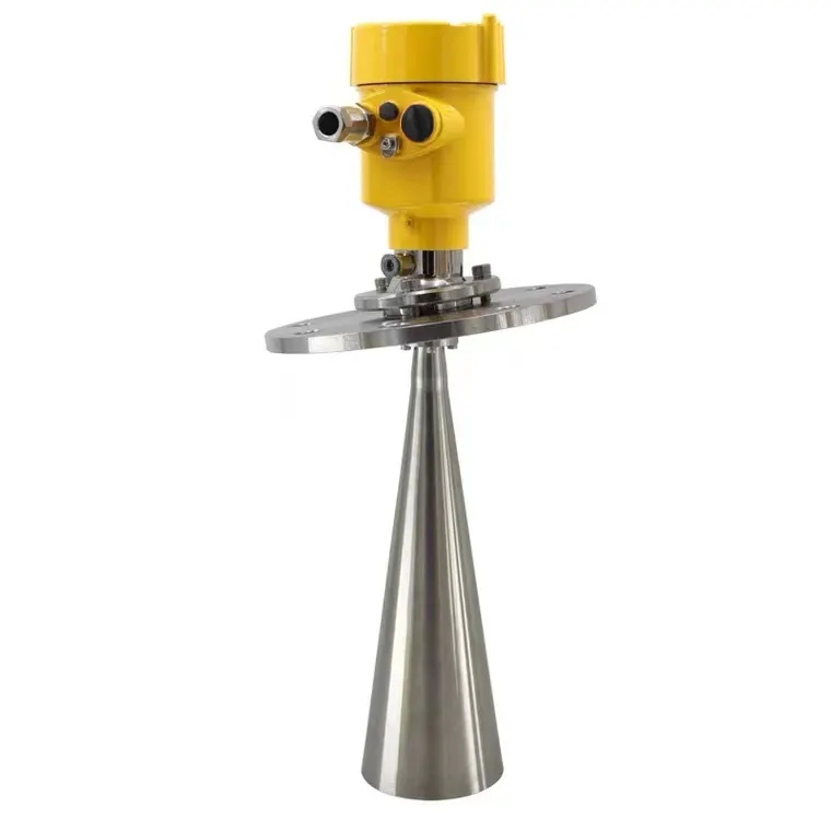
The level instruments illustrated in this article are relevant to storage, depth and open-channel arrangements. They are not interchangeable with a full-pipe flow meter. In particular, an ultrasonic water level sensor above a channel measures distance to the surface; it does not measure transit time through the water along a pipe-flow acoustic path.
| Technology | Suitable starting conditions | Selection limitation |
|---|---|---|
| Transit-time ultrasonic | An adequate acoustic path through the liquid; clamp-on versions can suit a pipe that cannot be cut. | Pipe material, wall thickness, lining, bubbles and deposits affect the installation. |
| Electromagnetic | Conductive liquid and a suitable full-pipe installation. | Confirm minimum conductivity, electrode and liner compatibility, grounding and empty-pipe behavior. |
| Mechanical | A specified water quality and operating range compatible with the moving measuring element. | Check debris, wear, pressure loss, low-flow performance and access for service. |
| Submerged ultrasonic Doppler | Enough acoustic scatterers, suitable submergence and a representative velocity sample. | Reflector distribution, fouling, sediment and the velocity profile affect the result. |
| Surface radar with level measurement | An open water surface with a suitable radar return and surveyed cross-section. | Surface velocity needs a site-appropriate conversion to cross-sectional mean velocity. |
| Level with a weir, flume or rating | A known hydraulic control or a validated stage-discharge relationship. | Backwater, submergence, geometry changes or deposits can invalidate the relationship. |
Transit-time and Doppler instruments are both ultrasonic, but they do not require the same water conditions. The U.S. Bureau of Reclamation's transit-time explanation identifies pipe dimensions, flow profile and acoustic signal strength as relevant considerations. Its Doppler discussion explains the dependence on moving acoustic reflectors and their distribution.
For electromagnetic measurement, sufficient conductivity is necessary, but there is no universal conductivity threshold or chemical-compatibility rating for every meter. Select the ordered construction against the actual liquid. A magnetic flowmeter explanation also identifies electrode deposits as a possible source of error.

Collect minimum, normal and maximum flow, including startup, low-demand irrigation and any reverse-flow condition. Check what the accuracy statement means at the low end: percent of reading, percent of span and an additive velocity term are different expressions. Display resolution does not establish an acceptable measurement uncertainty.
For a full circular pipe, Q = A x v and A = pi x D squared / 4, using the internal diameter. As an illustrative calculation, a 100 mm internal diameter gives an area of approximately 0.00785 m2. At 2 m3/h, average velocity is approximately 0.071 m/s; at 40 m3/h it is approximately 1.415 m/s. These are calculated operating points, not product performance ratings.
A meter selected only for the 40 m3/h condition may not be suitable for measuring the smaller flow. Conversely, reducing the meter bore to increase velocity can add hydraulic loss and require reducers. Compare both consequences against the selected meter's installation and pressure requirements. Use actual internal dimensions rather than assuming a nominal pipe designation is the bore.
Level is useful when it is connected to a valid hydraulic model. A properly installed measuring flume can relate head to discharge within its permitted operating conditions. A river section may have an established stage-discharge rating. Neither case means that any depth reading can be converted to flow with a generic formula.
Backwater is a common reason to question a level-only result. A downstream gate or rising receiving water can change velocity while the local depth remains similar. Sediment also changes the area available for flow. Recheck the method when the channel changes rather than assuming the sensor is the only possible cause of disagreement.
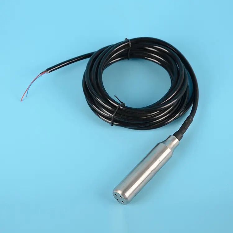
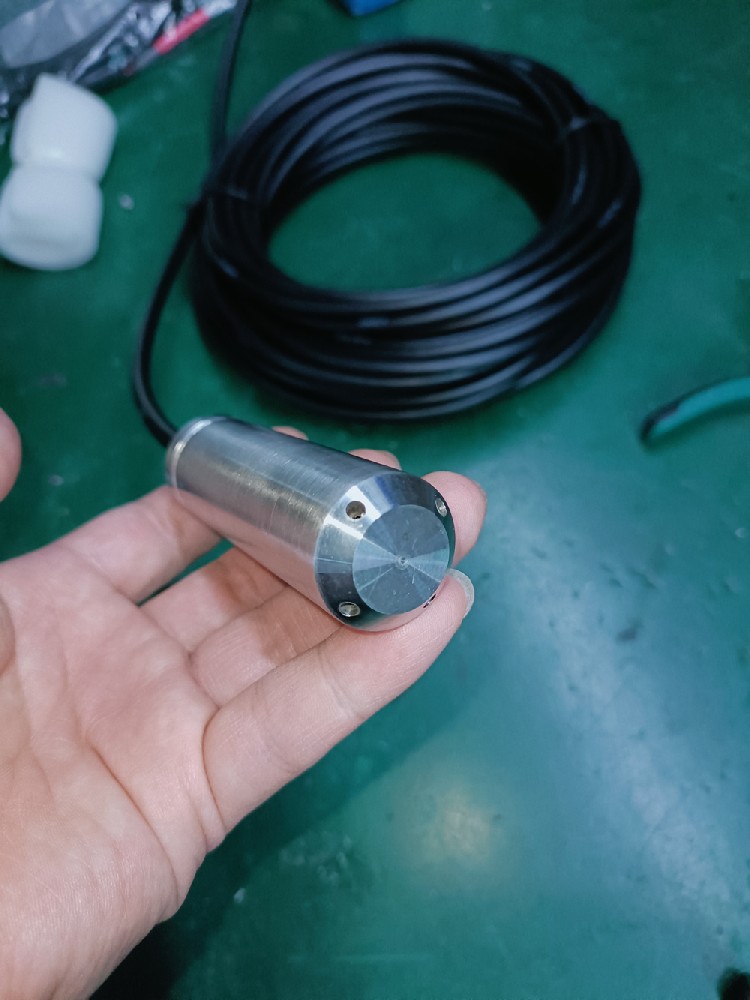
For an area-velocity arrangement, measure depth and velocity, then apply the surveyed section and the appropriate velocity conversion. A pressure level probe is one possible depth input. Its position, reference elevation and vent termination matter. Raising it above sediment without updating its elevation can shift every calculated area.
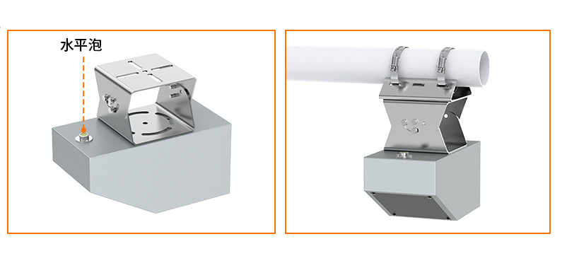
A NiuBoL non-contact radar flowmeter is an option for an exposed channel or river, not a clamp-on meter for a pressurized closed pipe. Its velocity and level channels have separate specifications. The following figures describe that radar configuration, not ultrasonic, electromagnetic or mechanical meters generally.
| Radar parameter | Specification | What it does not establish |
|---|---|---|
| Surface velocity | 0.1-20 m/s; stated accuracy +/-2%; resolution 0.01 m/s. | Accurate operation below 0.1 m/s or a complete discharge accuracy. |
| Level ranging | 0.1-65 m; stated ranging accuracy +/-1 mm; resolution 1 mm. | A 65 m velocity installation height or millimeter-level flow accuracy. |
| Supply and consumption | 10-30 V DC; maximum 1.3 W. | The power requirement of the logger, camera or communication equipment. |
| Communication | RS485 Modbus RTU. | A ready-made connection to every remote reporting platform. |
| Transmitter environment | -40 to +80 degrees C; 0-95% RH, non-condensing. | Permission to immerse an above-water assembly. |
| Protection and cable | Confirm the ordered enclosure, connector ingress rating, cable jacket and length. | A rating inferred from another instrument or from the word non-contact. |
Where water is too shallow or slow for a proposed area-velocity instrument, investigate a different measuring section, a suitable hydraulic control or another validated method. Do not select a large measuring range as a substitute for checking the smallest flow that matters to the project.

For a pipe meter, document nearby elbows, pumps, valves and reducers. Obtain the straight-run requirement for that design and the actual disturbance; a fixed 10D/5D rule is not valid for every instrument. Locate full-pipe measurement where the sensing section remains full and where air accumulation is controlled by the piping design.
Clamp-on access requires more than an exposed length of pipe. The team needs reliable pipe dimensions, suitable transducer mounting surfaces and a maintainable cable route. A lined or corroded pipe may need an installation assessment before committing to a non-intrusive retrofit.
In channels, the survey should include minimum depth, high-water clearance, sediment, vegetation, access and flow disturbances. A convenient mounting wall beside a gate can be an unsuitable velocity location. Check the measuring section while water is actually flowing, including the lower operating condition.
Keep personnel out of unsafe pipes, channels and operating machinery zones. Site isolation, access and work arrangements are part of the installation plan; a sensor selection article cannot authorize entry or work on a live hydraulic system.
Match the ordered output to the receiving equipment. RS485 Modbus RTU needs a compatible master, unique device addresses and the correct register format. A 4-20 mA input needs the actual scale and a defined treatment of out-of-range conditions. Pulse counting requires the pulse factor and a counter that retains or recovers volume as intended.
Check rate and volume independently. An illustrative constant flow of 12 m3/h for 15 minutes corresponds to 3 m3. This is a scaling check, not a calibration method. A PLC that applies seconds to an hourly flow rate without conversion can report a wrong total even when the instantaneous display looks correct.
During acceptance, compare the local reading, controller value and exported record at the same time. Test loss of power or communication and inspect how stale records and totalizer resets are represented. Use a suitable independent measurement for accuracy assessment. A second display reading the same transmitter is not an independent flow reference.
For a quotation, provide the water path, medium, operating flows, pipe or channel dimensions, pressure and temperature, installation constraints and interface. Ask NiuBoL to assess the relevant level and open-channel monitoring options. Request a separately identified full-pipe configuration where that is the requirement; do not assume the pictured level instruments include one.
No. Diameter defines only part of the application. Provide minimum and maximum flow, liquid properties, pipe condition and installation constraints. Verify the low operating point against the chosen accuracy statement.
No. Ultrasonic describes the measurement technology, not one mounting arrangement. Transit-time, submerged Doppler and above-water ultrasonic level instruments have different roles. Confirm the actual sensing path and installation.
Only as part of a valid flow calculation method. A depth signal alone is insufficient where velocity can change independently. Use a verified hydraulic relationship or a suitable area-velocity arrangement.
Assess the concentration, particle distribution and deposition risk. Doppler uses acoustic scatterers, while electromagnetic measurement requires conductive liquid and compatible construction. Neither category is automatically immune to deposits or installation errors.
No. A level-ranging capability does not establish a usable velocity return from the same height. Confirm the velocity installation, beam clearance and low-flow performance separately.
There is no category-wide interval. Set checks from the measurement duty, applicable project requirements, deposits, drift history and access. Investigate after a section change or an unexplained disagreement, not only on a calendar date.
No. Check units, scaling, signed values, register addressing and totalizer representation. Confirm how the selected SCADA system identifies stale or invalid observations before accepting the integration.
The measuring principle, bore, materials, pressure rating, outputs, accuracy requirement and installation work may differ. Compare the actual configuration and included commissioning, rather than treating diameter as a complete specification.
A suitable water flow meter matches the water path and the required operating range. Distinguish level from flow, verify the low-flow condition and check the installed measurement against an independent reference. A clear application description allows the supplier to propose an appropriate instrument without assigning one generic accuracy or installation rule to every technology.
Prev:Dissolved Oxygen Meters: Principles, Calibration and Uses
Next:Liquid Flow Meter Accuracy: Reading-Based Error vs Full Scale
Related recommendations
Sensors & Weather Stations Catalog
 Agriculture Sensors and Weather Stations Catalog-NiuBoL.pdf
Weather Stations Catalog-NiuBoL.pdf
Agriculture Sensors Catalog-NiuBoL.pdf
Water Quality Sensor Catalog-NiuBoL.pdf
Related products
 Combined air temperature and relative humidity sensor
 TDR Soil Moisture & Temperature Sensor for irrigation| RS485 |4-20mA| NBL-S-THR
 Soil pH sensor RS485 soil Testing instrument soil ph meter for agriculture |NBL-S-PH
 Wind Speed sensor Output Modbus/RS485/Analog/0-5V/4-20mA
 Tipping bucket rain gauge for weather monitoring auto rainfall sensor RS485/Outdoor/stainless steel
 Pyranometer Solar Radiation Sensor 4-20mA/RS485


Screenshot, WhatsApp to identify the QR code
WhatsApp number:+8615367865107
(Click on WhatsApp to copy and add friends)

