





— Blogs —
—Products—
 Consumer hotline +8618073152920
WhatsApp:+8615367865107
Address:Room 102, District D, Houhu Industrial Park, Yuelu District, Changsha City, Hunan Province, China
Product knowledge
Time:2024-06-29 22:03:15 Popularity:4288
How much area can a soil moisture sensor cover? A soil moisture sensor measures water content in a limited volume of soil around its sensing element. It does not directly measure the moisture content of an entire field, greenhouse or irrigation zone.
However, a sensor installed at a representative location can provide useful information for managing a much larger agricultural area. The area represented by one sensor depends on soil uniformity, irrigation distribution, crop rooting patterns, terrain and the purpose of the monitoring system.
There is no universal coverage value, such as a fixed number of square meters or hectares, that applies to every soil moisture sensor. The physical sensing volume and the agricultural area represented by a measurement are two different concepts.
A typical insertion-type soil moisture sensor measures conditions within a localized region surrounding its probe. The effective sensing volume depends on the sensor's electrode geometry, electromagnetic field, measurement principle and surrounding soil.
For agricultural irrigation management, one sensor location may represent a relatively uniform irrigation zone when its placement has been verified. A field containing different soil types, elevations, crops or watering patterns may require several monitoring locations.
The following distinctions are important:
| Term | Meaning |
|---|---|
| Sensing Volume | The localized volume of soil influencing the sensor's measurement. |
| Installation Depth | The depth at which the sensing element measures soil conditions. |
| Representative Area | The agricultural area for which a particular measurement point provides useful information. |
| Monitoring Location | A selected field position containing one or more sensors at appropriate depths. |
| Irrigation Management Zone | An area managed using similar irrigation rules or water application equipment. |
A sensor may measure a relatively small soil volume while providing information used to manage a much larger zone. That does not mean the instrument physically measures every part of that zone.
The sensing volume is the region of soil that contributes to a sensor's electrical or electromagnetic measurement.
Many agricultural soil moisture sensors use dielectric measurement methods, such as Frequency Domain Reflectometry (FDR), capacitance-based sensing or Time Domain Reflectometry (TDR).
These instruments measure the soil's dielectric response and use a calibration relationship to estimate volumetric water content (VWC).
The geometry of the sensor's electromagnetic field determines which parts of the surrounding soil influence the measurement. Different regions may contribute differently to the final reading.
Therefore, the sensing volume is not necessarily a sharply defined sphere or cylinder. It cannot always be determined by measuring the physical length of the probe rods.
Probe length and electrode arrangement influence the sensing structure, but they do not independently establish a universal measurement radius.
For example, a probe with sensing rods several centimeters long should not automatically be assigned a fixed cylindrical measurement volume using only the rod length and spacing.
The effective sensing volume depends on the sensor's actual design, operating principle and soil conditions. Where a precise sensing radius or measurement volume is required, use manufacturer-provided characterization or suitable validation data for that specific model.
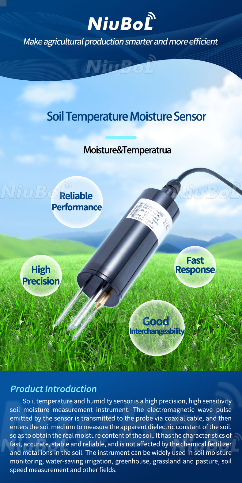
The NBL-S-THR Soil Temperature and Moisture Sensor is an example of an insertion-type agricultural probe. The physical size of its sensing rods should not be interpreted as a verified measurement area in square meters.
Installing a soil moisture sensor deeper changes the soil layer being monitored. It does not automatically increase the sensing volume or horizontal coverage of the instrument.
A sensor installed near the soil surface measures moisture conditions around its shallow sensing location. Another sensor installed deeper in the same field measures conditions in a different soil layer.
These readings may differ because rainfall, irrigation, evaporation, root water uptake and drainage affect soil layers differently.
The correct installation depth depends on the crop, effective rooting depth, irrigation method and monitoring objectives.
A sensor installed in the upper root zone can respond to changes near the soil surface, while deeper measurements can help show whether water has moved farther through the soil profile.
For example, after drip irrigation, a shallow sensor may show an increase in water content before a deeper sensor responds. The timing depends on soil hydraulic properties, applied water and sensor position.
Using several depths provides more information about the vertical distribution of soil moisture. It does not mean that one sensor has gained a larger horizontal measurement area.
The representative area is determined by how similar the soil and irrigation conditions are across the agricultural management zone.
A single sensor location may provide useful information for a relatively large uniform field. However, a smaller field containing different soil types or irregular irrigation coverage may require several monitoring points.
The representative area is therefore a management and sampling decision, not a fixed technical specification of the sensing probe.
Consider a field with relatively consistent soil texture, crop growth, topography and irrigation distribution.
A monitoring location selected in a representative part of this field may provide measurements suitable for assessing general root-zone moisture changes.
However, that sensor does not directly measure every square meter. Its usefulness for the broader field should be evaluated against field observations and, where appropriate, additional measurement locations.
Now consider a field containing both sandy and clay-rich soil.
These soils may have different water-retention characteristics, infiltration behavior and drying patterns. A reading from the sandy area may not accurately represent the conditions in the clay-rich area.
Separate monitoring locations may be needed for each important soil or irrigation management zone, even if the total field area is relatively small.
The main question is not simply how many hectares one sensor covers, but whether its readings represent the soil conditions relevant to the decisions being made.
The number of monitoring locations depends on several site characteristics.
| Factor | Effect on Sensor Placement |
|---|---|
| Soil Texture | Different soil types may require separate representative monitoring locations. |
| Field Topography | Slopes, depressions and elevated areas can have different water conditions. |
| Crop Type | Different crops can have different rooting depths and water requirements. |
| Irrigation Zones | Zones managed separately may benefit from separate sensor feedback. |
| Water Distribution | Uneven water application can produce different moisture patterns. |
| Rooting Depth | Multiple sensing depths may be needed to observe the effective root zone. |
| Monitoring Objective | General irrigation scheduling and detailed research require different measurement densities. |
| Required Confidence | Additional locations can help assess the variability and representativeness of measurements. |
A large field with uniform conditions does not necessarily require a fixed number of sensors per hectare. Conversely, a small experimental plot with substantial soil variation may require more intensive monitoring.
Irrigation method strongly influences where sensors should be installed. The position of the measurement point relative to water application is important for interpreting readings.
Drip irrigation applies water to localized regions of soil. Moisture conditions near the drip emitter can differ substantially from conditions farther away.
A probe should be installed in a representative part of the crop root zone, taking into account the expected wetting pattern and emitter placement.
A sensor installed directly beside an emitter may record an unusually wet location, while one placed outside the active wetting zone may remain relatively dry.
For sprinkler irrigation, sensor locations should represent normal water application and crop conditions.
Avoid unusual locations such as areas affected by overlapping spray patterns, wheel tracks or persistent irrigation nonuniformity unless those conditions are the actual monitoring objective.
Greenhouses may contain several cultivation zones with different crops, substrates, irrigation schedules or environmental conditions.
Separate monitoring locations can provide more useful information when the growing zones are managed independently or have substantially different moisture conditions.
In orchards and vineyards, sensor location should reflect tree or vine root distribution, irrigation emitter position and soil variation.
Monitoring several depths may help describe moisture changes through different portions of the root zone.
| Application | Placement Priority |
|---|---|
| Drip Irrigation | Emitter position, wetting pattern and root-zone location |
| Sprinkler Irrigation | Representative water application and soil conditions |
| Greenhouse | Cultivation zones, growing medium and irrigation arrangement |
| Orchard / Vineyard | Root distribution, emitter location and soil profile |
| Soil Research | Sampling design, variability and required measurement resolution |
There is no universal formula that converts agricultural field area into the correct number of soil moisture sensors.
A more reliable approach is to divide the field into management zones based on similar soil and irrigation characteristics, then select representative measurement locations within those zones.
Where possible, additional monitoring points can be used to determine whether the selected locations accurately represent conditions across the zone.
Identify soil variability: Review soil texture, depth, slope and known field differences.
Identify irrigation zones: Determine which areas receive similar water applications and are managed together.
Select representative locations: Avoid unusually wet, dry or disturbed positions unless they are intentionally monitored.
Choose measurement depths: Match the sensing depths to the crop root zone and required observations.
Check representativeness: Compare readings with other locations or suitable field observations during irrigation and drying periods.
Expand monitoring where necessary: Add locations when important differences are not represented by the existing sensors.
For example, a single monitoring location containing sensors at two depths provides two vertical measurements at one field position. It does not provide the same spatial information as two monitoring locations positioned in different areas of the field.
If a project requires detailed soil moisture maps, a larger sampling network or additional measurement methods may be necessary. Fixed point sensors alone do not continuously map every part of the surrounding land.
Proper sensor installation and data interpretation are necessary to obtain useful readings from each monitoring point.
The sensing element should maintain appropriate contact with the surrounding soil. Air gaps, stones, disturbed soil and damaged probes can affect the electrical measurement.
Follow the installation instructions for the selected model. For some probes, insertion into an undisturbed soil pit wall can be used to position the sensing element at the required depth.
Field edges, wheel tracks, depressions, unusual soil patches and areas receiving atypical irrigation may produce measurements that do not reflect general conditions.
Such locations may still be useful for specific research, but their measurements should not be assumed to represent the entire management zone.
Dielectric soil moisture readings may be influenced by soil texture, bulk density, temperature, salinity and calibration.
When comparing different soil types or locations, confirm that the sensor's calibration and specified operating conditions are suitable for the application.
Monitoring measurements over several irrigation, rainfall and drying periods can help determine whether sensor placement is useful for irrigation management.
The observation interval should be selected according to irrigation frequency, measurement objectives and the available data acquisition system.
Soil moisture sensors typically require inspection of their installation, cable and measurement behavior. Customer recalibration is not automatically required for every factory-calibrated electronic probe; follow the model-specific maintenance instructions.
Communication range and soil sensing volume are completely different characteristics.
An RS485 soil moisture sensor measures conditions in the soil surrounding its sensing element and sends data to compatible receiving equipment.
A suitable 4G, Ethernet, Wi-Fi or LoRaWAN gateway can make those readings available from a remote location. However, this communication capability does not increase the physical volume of soil being measured.
Local Soil Measurement → Sensor Output → Data Logger / Gateway → Monitoring Platform
For large agricultural projects, additional sensor locations improve spatial measurement coverage. Network gateways improve data communication and accessibility.
A1. There is no fixed number of square meters for every sensor. A probe measures a localized soil volume, while the agricultural area its readings can represent depends on soil uniformity, irrigation patterns and sensor placement.
A2. The effective sensing region depends on electrode geometry, measurement technology and soil conditions. A precise radius should only be used when supported by data for the specific sensor model.
A3. Not necessarily. Greater installation depth changes the monitored soil layer. It does not automatically increase the sensor's sensing volume or horizontal coverage.
A4. One representative sensor location can provide useful irrigation information for a relatively uniform management zone. However, it does not directly measure every part of the farm. Multiple locations may be needed when soil, crop or irrigation conditions vary.
A5. The required number depends on irrigation zones, soil variability, emitter positions, rooting depth and monitoring objectives. There is no universal sensor-per-hectare rule for every drip irrigation system.
A6. No. A multi-depth sensor provides vertical measurements at one location. Separate monitoring locations are required to observe spatial differences across a field.
A7. No. Wireless communication increases data transmission capability, not the volume of soil being sensed. Larger measurement networks require appropriately positioned additional sensors.
NiuBoL provides soil moisture, temperature, EC and integrated soil monitoring instruments for agricultural irrigation, greenhouse cultivation, environmental monitoring and data acquisition systems.
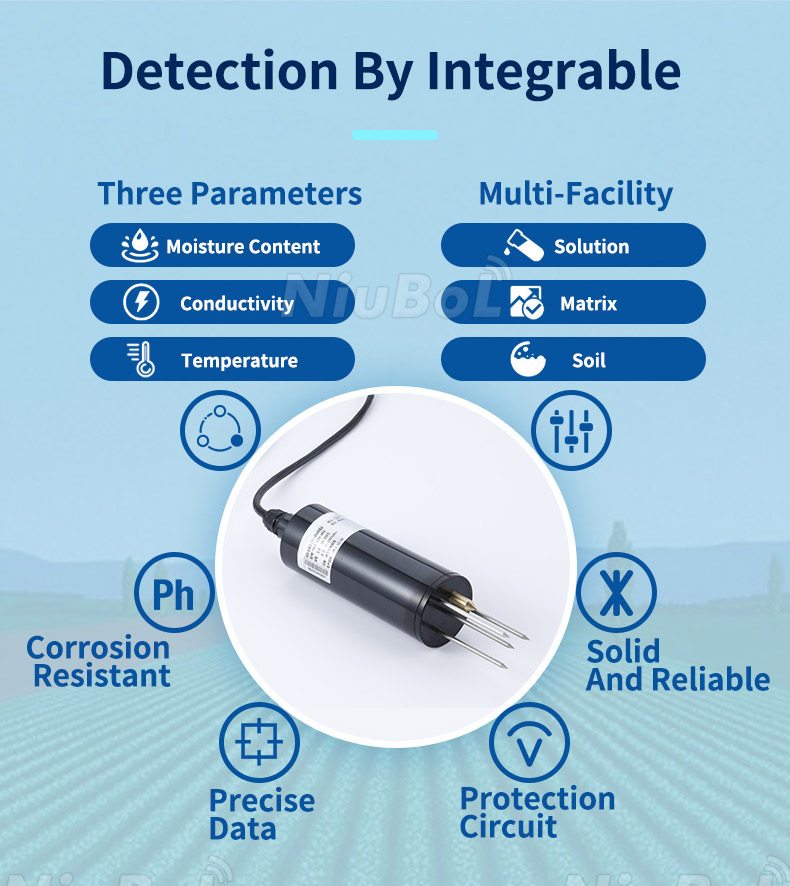
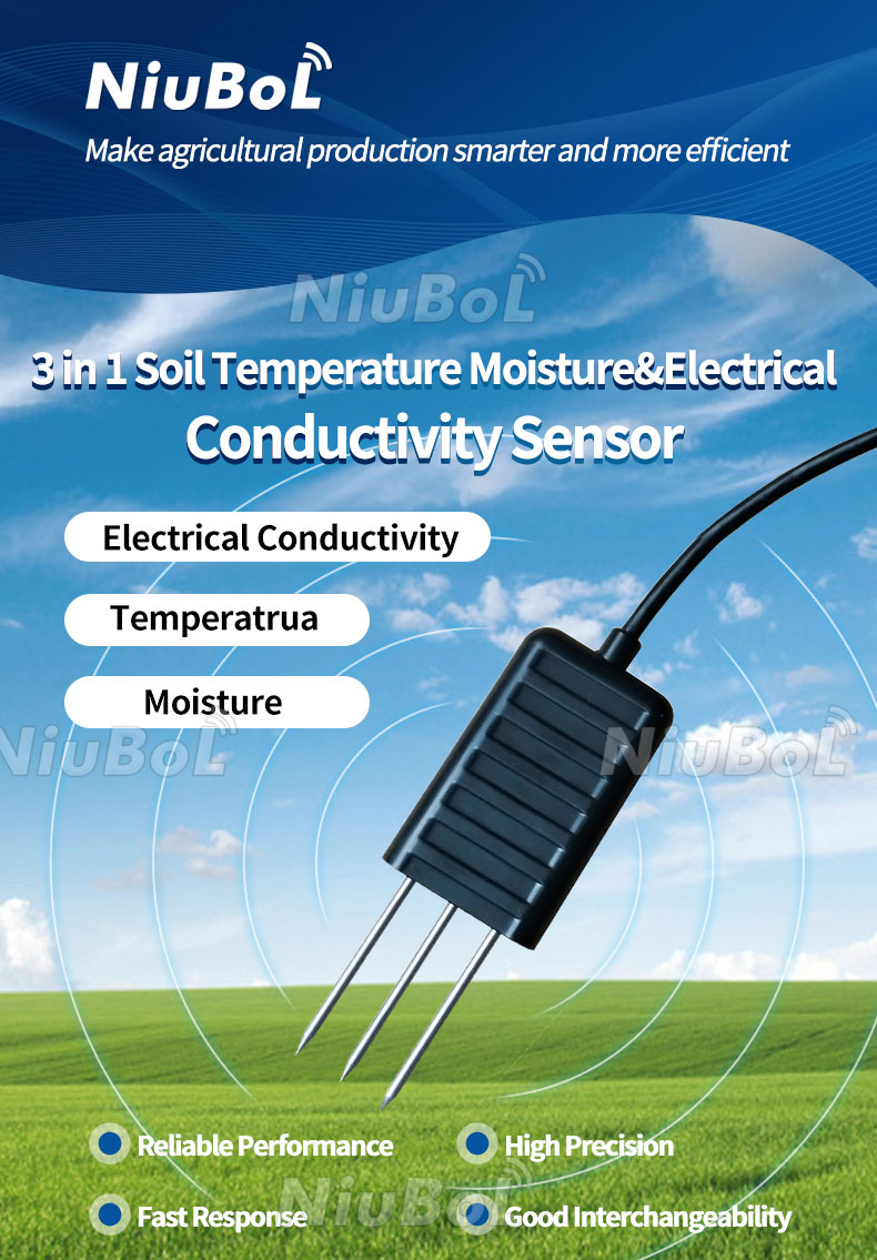
Available instruments include the NBL-S-THR Soil Temperature and Moisture Sensor, NBL-S-TMC Soil Temperature, Moisture and EC Sensor and additional soil monitoring sensors.
For a monitoring project, provide the field or greenhouse layout, soil types, crop, irrigation arrangement, desired measurement depths, number of management zones, sensor output, power supply and data acquisition requirements.
Sensor quantity and location can then be evaluated according to the actual measurement objectives rather than an assumed fixed coverage area.
The following original NiuBoL technical documents provide specifications and installation information for selected soil monitoring instruments.
 NBL-S-THR-Soil-temperature-and-moisture-sensors-Instruction-Manual-V4.0.pdf
NBL-S-TMC-Soil-temperature-and-moisture-conductivity-sensor.pdf
NBL-S-TM-Soil-temperature-and-moisture-sensor-Instruction-Manual-4.0.pdf
NBL-S-TMCS-Soil-Temperature-Humidity-Conductivity-and-Salinity-Sensor.pdf
7-in-1-Soil-Composite-Sensor-Manual.pdf
8-in-1-Soil-Composite-Sensor-Manual.pdf
Use the manual for the selected model to confirm sensing technology, operating conditions, measurement range, output interface, cable length and installation requirements.
Related recommendations
Sensors & Weather Stations Catalog
 Agriculture Sensors and Weather Stations Catalog-NiuBoL.pdf
Weather Stations Catalog-NiuBoL.pdf
Agriculture Sensors Catalog-NiuBoL.pdf
Water Quality Sensor Catalog-NiuBoL.pdf
Related products
 Combined air temperature and relative humidity sensor
 TDR Soil Moisture & Temperature Sensor for irrigation| RS485 |4-20mA| NBL-S-THR
 Soil pH sensor RS485 soil Testing instrument soil ph meter for agriculture |NBL-S-PH
 Wind Speed sensor Output Modbus/RS485/Analog/0-5V/4-20mA
 Tipping bucket rain gauge for weather monitoring auto rainfall sensor RS485/Outdoor/stainless steel
 Pyranometer Solar Radiation Sensor 4-20mA/RS485


Screenshot, WhatsApp to identify the QR code
WhatsApp number:+8615367865107
(Click on WhatsApp to copy and add friends)

