





— Blogs —
—Products—
 Consumer hotline +8618073152920
WhatsApp:+8615367865107
Address:Room 102, District D, Houhu Industrial Park, Yuelu District, Changsha City, Hunan Province, China
Product knowledge
Time:2026-03-04 09:48:24 Popularity:739
Industrial VOC monitoring starts with defining the result: a local solvent-vapor trend, total hydrocarbons in a process exhaust, non-methane hydrocarbons, or the concentration of a named compound. These are not interchangeable measurements. A general TVOC sensor can support ambient monitoring, but a fixed-source emissions project needs an analyzer and sampling system matched to the required method. Selecting a device by its ppm range alone can leave the project measuring the wrong quantity.
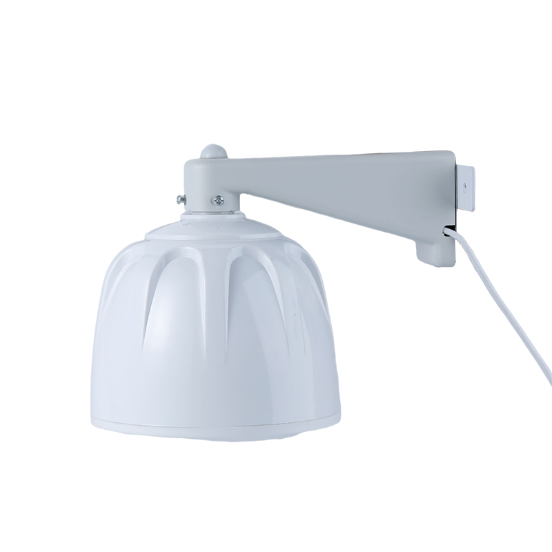
The NiuBoL TVOC and H2S sensor shown above is an ambient gas-monitoring product, not a heated stack-sampling system. Keeping those equipment roles separate helps contractors specify the appropriate instrument before designing the cabinet, power supply and data connection.
| Required result | Measurement question | What a general VOC reading cannot establish |
|---|---|---|
| Ambient TVOC trend | Has the response to a mixture of detectable vapors changed at this point? | The concentration of every individual solvent or its source |
| Total hydrocarbon response | What combined response does the analyzer report on its stated calibration basis? | Non-methane concentration without methane discrimination |
| Non-methane hydrocarbons, NMHC | How are methane and total hydrocarbons separated or measured? | A valid NMHC result from an unspecified total-VOC channel |
| A named compound | Does the method distinguish that compound in this gas mixture? | Compound-specific concentration from a nonspecific detector alone |
| Emission mass rate | Are concentration and exhaust flow on compatible reference conditions? | kg/h from a concentration value without flow information |
A coating line may need a solvent trend during production changes, while a stack-monitoring contract may require a defined carbon-based result. A pharmaceutical process using several solvents may need compound-specific analysis. Write the measurand and reporting basis into the inquiry rather than asking only for a "VOC monitoring system."
A photoionization detector uses ultraviolet light to ionize compounds that respond at the lamp's energy. Its response depends on the chemical mixture and calibration gas. A single PID signal does not identify each compound; changing solvents can change the indicated concentration even when the total amount of vapor is similar. Lamp contamination and humidity also need attention. The OSHA Technical Manual, Section II, Chapter 3, explains these limitations and response-factor considerations for photoionization detectors.
Use a PID proposal only after checking that the target compounds respond to the selected lamp and that the calibration basis is appropriate. For an unknown or changing mixture, record the result as the defined instrument response. Applying one solvent's correction factor to every production recipe can create a false comparison between batches.
A flame ionization detector produces a response from organic compounds in a hydrogen flame. EPA Method 25A is one example of a method for total gaseous organic concentration. Its results are expressed relative to an appropriate calibration gas or as carbon; naming the detector does not by itself establish method conformity.
For NMHC, the system must distinguish methane from the total response, for example through an appropriate separation and measurement arrangement. Check whether the analyzer reports both channels on the same basis and how it handles sampling cycles. Two numbers from different calibration bases must not simply be subtracted.
As an illustrative unit conversion, 2 ppmv of propane is 6 ppmv as carbon because propane contains three carbon atoms. This does not mean a PID reading of 2 ppm is automatically 6 ppmC. The compound, calibration and reporting convention must be known before making that conversion.
A stack sample is not ambient air. Temperature, water vapor, particles and condensable compounds affect how it can be transported to an analyzer. Define the sample route from the probe to the measurement cell, including the filter, line, valves and any conditioning equipment. Specify which compounds must remain in the gas phase through that route.
A condenser is not a universal improvement. Cooling may remove water but also alter the recoverable concentration of soluble or condensable compounds. Conversely, a heated system needs an appropriate temperature throughout the sample path, not merely a heater at one end. The Method 25A sampling description uses a heated line and filter; it should not be converted into a blanket instruction to cool every VOC sample.
Investigate slow response at the inlet as well as inside the analyzer. A short detector response specification excludes transport delay unless the complete system is tested. For a switching arrangement serving two locations, include line flushing, stabilization and analysis time in the interval between valid results. Do not label alternating measurements as simultaneous inlet and outlet observations.
Request a recovery check through the installed sample route, using the method and gases appropriate to the project. An analyzer that passes a direct calibration check can still lose sample in a contaminated line or leaking fitting. That distinction matters when commissioning a replacement analyzer on an older sampling system.
A PLC or data logger should receive the concentration, unit, measurement timestamp and relevant validity information. Where supported, include calibration, warm-up, sample-flow fault, analyzer fault and maintenance states. A normal-looking number from a unit in calibration mode is not a process observation.
RS485 Modbus RTU compatibility requires more than a matching connector. Compare the analyzer's register map with the acquisition software: channel identity, word order, scaling and status bits all matter. Check the analog fallback separately if 4-20 mA is used. The current-loop span must correspond to the selected analyzer range, and fault-current behavior must be interpreted correctly.
NiuBoL data acquisition gateways can be considered for compatible industrial instruments. The acquisition configuration must be checked against the actual analyzer protocol. Network forwarding does not change a sensor's measurement method, create missing methane separation or make its data acceptable for a reporting program.

For emission-rate calculations, align the concentration and exhaust-flow reference conditions. An illustrative concentration of 50 mgC/m3 combined with 2,000 m3/h gives 100,000 mgC/h, or 0.10 kgC/h, only when both quantities use compatible conditions. It is a carbon mass rate, not automatically the mass rate of a particular solvent.
Similarly, treatment efficiency cannot always be calculated from concentration reduction alone. If inlet and outlet gas flows differ, calculate the corresponding mass rates before comparing them. Account for the sampling delay between the two locations; a transient production change can otherwise appear as a temporary efficiency gain or loss.
An ambient module is useful for a separate environmental monitoring point when its response, range and exposure conditions suit the application. It should not be connected directly to hot, wet exhaust simply because the same controller can read both devices. The following specifications apply to the NiuBoL TVOC/H2S product, not to PID or FID analyzers as a class.
| Ambient sensor parameter | Specified value | Selection implication |
|---|---|---|
| TVOC range | 0-40 ppm | Check expected concentrations and the calibration basis before using the channel. |
| H2S range | 0-10 ppm | A separate gas channel; do not combine it with the TVOC value. |
| Power supply | 12-24 V DC | Use the rating of this sensor, not an assumed analyzer-cabinet load. |
| Output | RS485, Modbus RTU | Connect through a configured local acquisition port. |
| Response time | T90 at or below 30 seconds | Not a complete remote alarm-delivery time. |
| Operating conditions | -20 to 50 degrees C; at or below 95% RH, non-condensing | Unsuitable for direct exposure to a condensing stack sample. |
| Protection | IP65 | This is not an explosion-protection approval. |
The supply package and calibration documentation should identify the sensing configuration. Do not infer a PID lamp specification from the word TVOC. The ambient sensor above, a PID monitor and an FID system are separate instruments with different operating and maintenance requirements.
A compact environmental station can collect temperature, humidity and compatible external sensor data around an industrial site. These observations may help interpret local vapor trends. They do not measure stack flow or replace the analyzer's sample conditioning. Place environmental channels and process-emissions channels in clearly named groups on the receiving platform.
Solar sizing for an ambient node cannot be transferred to a heated FID installation. The latter may include a heated probe and line, pumps, analyzer, enclosure climate control and fuel or utility-gas equipment. Determine the complete operating and start-up loads. No fixed number of backup days can be promised without the selected loads, available energy and duty cycle.
For hazardous areas, require equipment approval appropriate to the actual location and installation. Review the complete arrangement, including sensors, power supplies and cable entries. IP65, a metal enclosure or RS485 communication is not a substitute for that assessment.

Not on the basis of its name or range. NMHC requires defined methane handling and a consistent reporting basis. Select the measurement method required by the project before comparing interfaces or prices.
No. Two nonspecific detector responses do not provide full chemical identification. If a named compound is required, specify an appropriate selective or separation-based method and evaluate interferences in the actual mixture.
Separate the analyzer, sampling probe, line conditioning, utility gases, enclosure, acquisition equipment and commissioning work. State the target compounds, reporting units, concentration range, sample temperature and moisture. Otherwise low-cost proposals may omit equipment needed to preserve the sample.
Often, but verify the register map and required status channels first. Supply a sample data definition to the integrator and test normal, calibration and fault states. Concentration-only communication is insufficient when invalid measurements must be excluded.
No. Environmental trend monitoring and a protective shutdown have different requirements. Do not use an ordinary TVOC module as a substitute for a properly specified gas-safety system. Protective actions need a separate engineering and safety assessment.
Industrial VOC monitoring works when the instrument, sample route and reported result describe the same measurement. Decide whether the project needs ambient trends, total hydrocarbons, NMHC or compound-specific analysis before selecting PID, FID or another method. For the environmental sensing and data-acquisition portion, send NiuBoL the sensor or analyzer interfaces and site conditions so the suitable module and gateway scope can be assessed without confusing it with a complete stack-analysis package.
Prev:Small Water Quality Monitoring Buoy: Test the Loaded Assembly Before Launch
Next:Types of Soil Sensors: Continuous Probes vs Field Tests
Related recommendations
Sensors & Weather Stations Catalog
 Agriculture Sensors and Weather Stations Catalog-NiuBoL.pdf
Weather Stations Catalog-NiuBoL.pdf
Agriculture Sensors Catalog-NiuBoL.pdf
Water Quality Sensor Catalog-NiuBoL.pdf
Related products
 Combined air temperature and relative humidity sensor
 TDR Soil Moisture & Temperature Sensor for irrigation| RS485 |4-20mA| NBL-S-THR
 Soil pH sensor RS485 soil Testing instrument soil ph meter for agriculture |NBL-S-PH
 Wind Speed sensor Output Modbus/RS485/Analog/0-5V/4-20mA
 Tipping bucket rain gauge for weather monitoring auto rainfall sensor RS485/Outdoor/stainless steel
 Pyranometer Solar Radiation Sensor 4-20mA/RS485


Screenshot, WhatsApp to identify the QR code
WhatsApp number:+8615367865107
(Click on WhatsApp to copy and add friends)

