





— Blogs —
—Products—
 Consumer hotline +8618073152920
WhatsApp:+8615367865107
Address:Room 102, District D, Houhu Industrial Park, Yuelu District, Changsha City, Hunan Province, China
Product knowledge
Time:2025-10-15 14:12:52 Popularity:2540
Ultrasonic water level sensor limitations usually become visible as an unstable reading, a fixed false reading or a lost echo. Non-contact measurement keeps the probe out of the water, but sound must still travel through the tank atmosphere and return from the intended surface. Separate an echo problem from a reference, scaling or communication fault before changing the sensor.
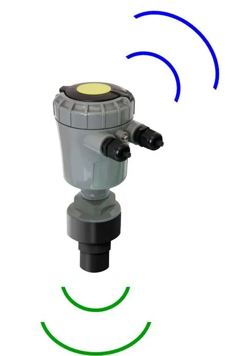
Ultrasonic level measurement is useful when there is access above the liquid and a suitable acoustic path. It can reduce immersion-related exposure and allow service without retrieving a submerged cable. Those advantages do not remove the need to inspect the transducer face or establish whether the surface can return a usable signal.
Compare a safe independent level observation, the instrument's local distance or level value, and the controller's displayed value. If the local measurement follows the water but the PLC does not, investigate address, scaling, register interpretation and update time. Echo processing is unlikely to correct a receiver-side error.
If the instrument's own value is fixed or erratic, collect the operating condition at that moment: liquid position, filling or pumping state, foam, transducer condition and available diagnostic status. A problem that occurs only during filling needs a different investigation from a constant offset present at every level.
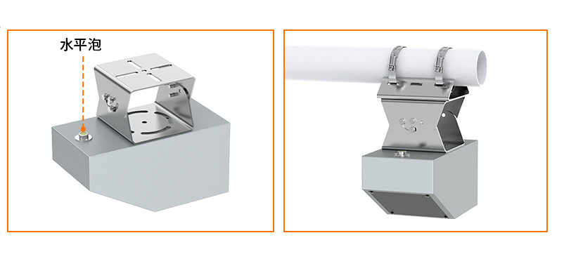
The equipment above is a radar surface-velocity instrument, not an ultrasonic level transducer. It illustrates why instrument identification matters during troubleshooting. Confirm the physical quantity and exact model before applying a wiring diagram, diagnostic code or replacement recommendation.
| Observed pattern | Possible explanation | Practical check |
|---|---|---|
| Consistent offset across the operating band | Wrong mounting reference, zero or distance-to-level conversion | Measure from the specified acoustic reference and compare at more than one known level. |
| Reading becomes fixed near one value | A structure is being tracked, the value is being held after echo loss, or the receiver has stopped updating | Compare diagnostics and timestamps; inspect the path for fittings near the reported distance. |
| Dropout when water rises close to the sensor | Surface enters the blocking distance or spray wets the face | Check the maximum-level clearance against the exact transducer's installation limits. |
| Variation during filling or aeration | Turbulence, foam, inlet interference or changing acoustic conditions | Compare quiet and active conditions without changing several settings at once. |
These patterns guide inspection; they do not prove a fault by themselves. Avoid entering a tank or opening an unsafe chamber merely to obtain a reference. Use the site's approved access and test arrangements.
The distance calculation uses acoustic travel time and an assumed sound speed. A temperature sensor near the transducer can improve compensation for local air temperature. It does not necessarily represent a strong temperature gradient throughout a tall tank or establish the sound speed of an unusual gas mixture.
Look for a correlation between the discrepancy and heating, ventilation, sunlight or vapour release. Record the liquid reference and available temperature values at the same time. Do not assign a universal millimetre accuracy to every compensated ultrasonic transmitter, or assume a higher nominal range resolves an atmospheric problem.
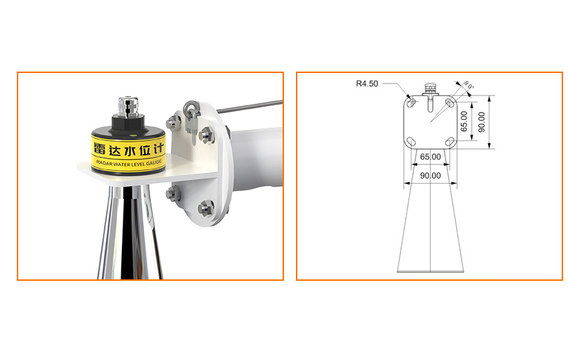
The radar level instrument above uses electromagnetic measurement rather than sound. It avoids dependence on acoustic sound speed, but the NiuBoL radar level sensor still needs a suitable reflecting surface and clear geometry. It is a candidate for assessment, not proof that every difficult ultrasonic application can be solved by exchanging the head.
Foam can weaken the acoustic return or change the effective reflecting surface. Inspect when the troublesome operating condition is present; a clear-water demonstration does not characterize the foaming process. Condensation or deposits on the face may also interfere. Use the selected instrument's cleaning procedure and check whether any heating or surface treatment is actually included rather than assuming it is standard.
A ladder, brace or mounting neck may produce an unwanted reflection. Align the transducer as specified and assess clearance through the full operating range. A stilling pipe can introduce its own echoes and restrictions. Its use must be approved for the instrument and process, not improvised as a general anti-interference device.
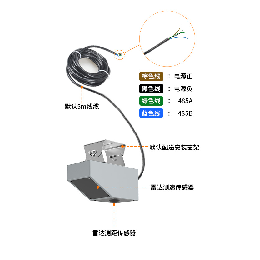
The radar velocity assembly above is not a stilling-pipe accessory or ultrasonic module. In a mixed monitoring cabinet, label the sensor cables and confirm the intended input channel before replacing a suspect instrument. A correct electrical connection to the wrong quantity can still produce a plausible-looking number.
Damping can reduce short-term variation, but it also delays the displayed response. It cannot turn an echo from a ladder into a water-surface measurement. Compare the undamped or diagnostic result where available, and document each setting change so improvements can be separated from temporary changes in the process.
Test how the selected transmitter and controller handle loss of echo. A frozen last-good value should have a recognizable invalid or stale status. Do not let a controller interpret that held value as evidence that a tank remains safely within its operating band.
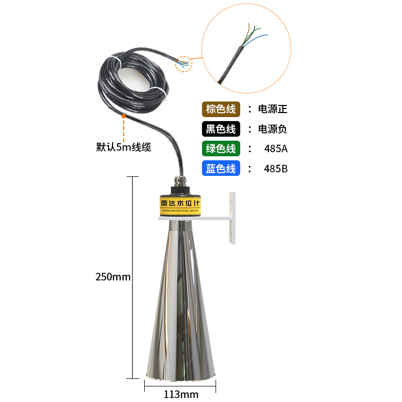
This radar level instrument and cable drawing shows a separate product family. For that NiuBoL configuration, the published standard range is 0.1-65 m, the dead zone is approximately 0.1 m, and the output is RS485 Modbus RTU with DC 10-30 V supply. These are radar figures, not specifications for the ultrasonic illustration at the start of this article.
Retain ultrasonic measurement when a corrected reference, suitable mounting or removal of a specific obstruction restores a stable, verifiable result across the operating cycle. Consider another method when persistent foam, atmosphere or access conditions prevent a valid return despite a compliant installation.
A hydrostatic probe avoids an overhead acoustic path but introduces liquid contact, density dependence and pressure-reference requirements. Radar avoids acoustic sound-speed dependence but still requires application checks. Compare alternatives against the recorded failure condition, not a generic claim of higher accuracy.
Only if the variation is acceptable surface movement and the resulting delay is suitable. Damping does not correct a wrong echo or blocked path. Verify the measured surface first.
Some configurations hold the last valid value for a period. Inspect the model's failure settings and status output, then test the receiving system so an invalid held value is not mistaken for a current reading.
No. RS485 Modbus RTU defines the communication framework, not a universal measurement register map. Obtain the exact unit's addresses, data types, scaling and status definitions.
Reproduce the difficult condition and compare against a known reference through representative levels. Include filling, foam or temperature changes responsible for the original failure, rather than accepting a single static reading.
Provide the model, firmware or configuration identification, mounting dimensions, expected level band and a time-aligned trend. Include local and receiver readings, available diagnostics and photos of the acoustic path taken under safe access conditions.
Evaluate ultrasonic water level sensor limitations through observable failure patterns. Establish whether the error is in the echo, reference or receiving system, then address the specific cause. A verified correction is more useful than generic filtering, and a replacement should be tested under the conditions that defeated the original measurement.
Prev:Water Level Sensor Specification: Prepare an Application Data Sheet
Next:Pool Water Level Sensor: Balance-Tank Monitoring and Refill Control
Related recommendations
Sensors & Weather Stations Catalog
 Agriculture Sensors and Weather Stations Catalog-NiuBoL.pdf
Weather Stations Catalog-NiuBoL.pdf
Agriculture Sensors Catalog-NiuBoL.pdf
Water Quality Sensor Catalog-NiuBoL.pdf
Related products
 Combined air temperature and relative humidity sensor
 TDR Soil Moisture & Temperature Sensor for irrigation| RS485 |4-20mA| NBL-S-THR
 Soil pH sensor RS485 soil Testing instrument soil ph meter for agriculture |NBL-S-PH
 Wind Speed sensor Output Modbus/RS485/Analog/0-5V/4-20mA
 Tipping bucket rain gauge for weather monitoring auto rainfall sensor RS485/Outdoor/stainless steel
 Pyranometer Solar Radiation Sensor 4-20mA/RS485


Screenshot, WhatsApp to identify the QR code
WhatsApp number:+8615367865107
(Click on WhatsApp to copy and add friends)

