





— Blogs —
—Products—
 Consumer hotline +8618073152920
WhatsApp:+8615367865107
Address:Room 102, District D, Houhu Industrial Park, Yuelu District, Changsha City, Hunan Province, China
Product knowledge
Time:2025-10-15 15:10:49 Popularity:2332
A pool water level sensor should measure the part of the hydraulic system that the controller needs to manage. In an overflow pool, the balance tank often provides useful information about available water, but its operating level changes with bathers and circulation. In a skimmer pool, the required sensing point and control logic are different. Neither arrangement justifies a universal refill threshold.
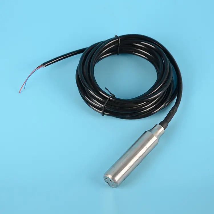
Commercial pool operators need to distinguish normal displacement, evaporation, backwashing and abnormal loss. A level probe can support that task, but it cannot identify the cause from one reading. Automatic replenishment also needs a controller, a suitable water valve and defined behavior when the measurement or valve fails.
In an overflow installation, water displaced by bathers enters the balance tank and may return through the circulation system. If a controller replenishes every brief decrease in tank level, the system can add water unnecessarily during changing occupancy. Assess the empty-pool condition, normal bather load, pump operation and backwash sequence before fixing thresholds.
A skimmer pool does not necessarily have that buffer. The desired waterline must remain consistent with the skimmer and circulation design. A remote chamber may provide a quieter measurement location only if it remains hydraulically connected, vented where required and free from blockage. A chamber that lags behind the pool can hide a rapid loss.
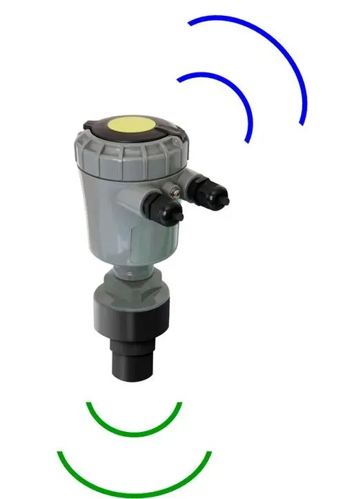
The non-contact ultrasonic arrangement above illustrates one measurement option. Keep the highest expected surface outside the selected instrument's blocking distance. Avoid inlet jets, spray and persistent foam. A narrow stilling tube is not an automatic cure: its dimensions and internal echoes must be compatible with the transducer.
A float switch can operate a refill controller; it is incorrect to dismiss floats as unsuitable for replenishment. Two switching points or an appropriate switching differential can provide start and stop conditions. Mechanical access, sticking, cable movement and the controller's input requirements still need consideration.
A continuous transmitter provides a level trend and adjustable thresholds. That can help a facilities team compare overnight loss or balance-tank behavior, but it adds configuration and signal-validation requirements. More displayed decimals do not guarantee better control when waves and occupancy dominate the signal.
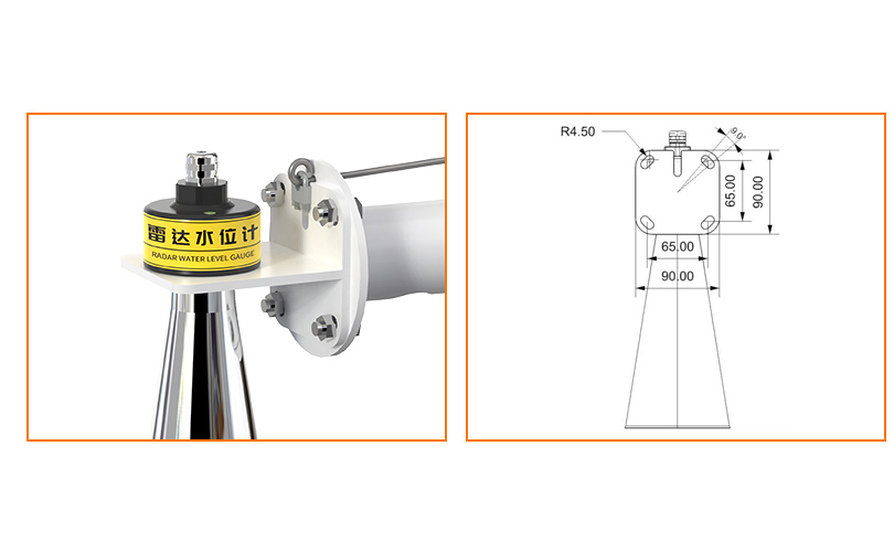
The radar level instrument above is another non-contact option, distinct from ultrasonic measurement. Choose it for a justified measurement requirement and suitable installation geometry, not on the assumption that all pool sites need long-range radar.
| Option | Useful pool duty | Check before specifying |
|---|---|---|
| Float switch | Defined high or low switching point; refill start/stop through a controller | Operating differential, free movement, mounting and failure response |
| Submersible hydrostatic transmitter | Continuous level in a compatible balance tank or chamber | Chemical compatibility, selected span, diaphragm location and vented cable termination |
| Ultrasonic transmitter | Continuous non-contact measurement above a suitable surface | Blocking distance, condensation, foam, beam clearance and invalid-echo indication |
| Radar transmitter | Non-contact measurement where its beam and operating limits fit | Mounting clearance, surface return, environment and total system cost |
The NiuBoL NBL-L-WLPS hydrostatic water-level transmitter provides RS485 Modbus RTU, DC 10-30 V supply and IP68 protection, with the measuring range selected for the project. Its stated medium requirement is water or other liquid non-corrosive to stainless steel. Provide disinfectant chemistry, concentrations, salt content and cleaning conditions for compatibility review; IP68 is not a chlorine-resistance specification.
Use separate start and stop thresholds with an appropriate differential, and define any persistence delay from observed tank movement. Do not copy a 1 cm trigger into every installation. The normal working band must accommodate occupancy and hydraulic behavior while protecting the required operating reserve.
The controller should also limit a refill event by time or another agreed criterion. If level does not recover while the valve is commanded open, the possible causes include an empty supply, a failed valve, abnormal water loss or a measurement fault. Continuing to refill indefinitely hides the problem.
Specify a separate high-level stop and the response to power loss or invalid data with the pool-system designer. Do not depend on a cloud connection for essential local protection. For remote reporting, test the water-level alarm path separately. Pump dry-running protection also needs to follow the pump and hydraulic design; a sensor placed at an arbitrary pipe location is not sufficient.
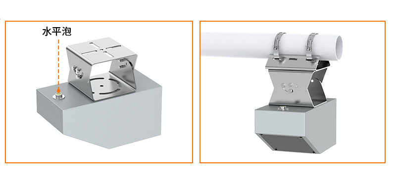
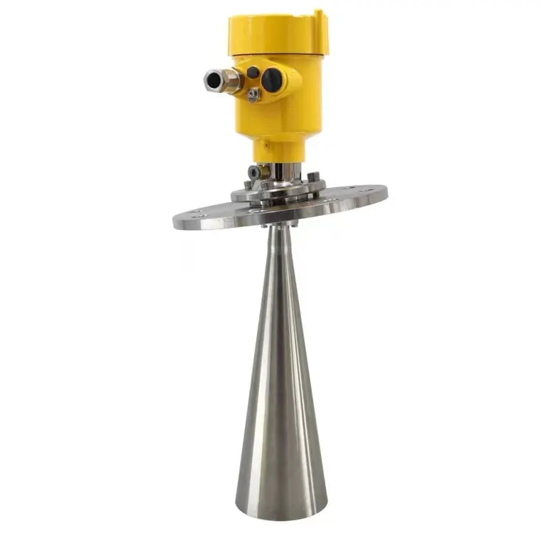
The radar surface-velocity instrument above measures moving water, not pool depth. Circulation and replenishment volume are separate quantities from level. A velocity instrument intended for open water should not be treated as a closed-pipe pool flowmeter or connected as the refill-level input.
Compare similar operating periods and keep refill, backwash and occupancy records alongside level. For a simple constant-area tank, a small level change can be converted to volume using surface area, but that does not account for water temporarily held elsewhere in the pool circuit.
If loss appears abnormal, first verify the sensor and then examine the hydraulic system. Evaporation, splash-out and maintenance discharge must be distinguished from leakage. Automatic leak diagnosis requires a defined method and additional operating information; it is not an inherent feature of a level transmitter.
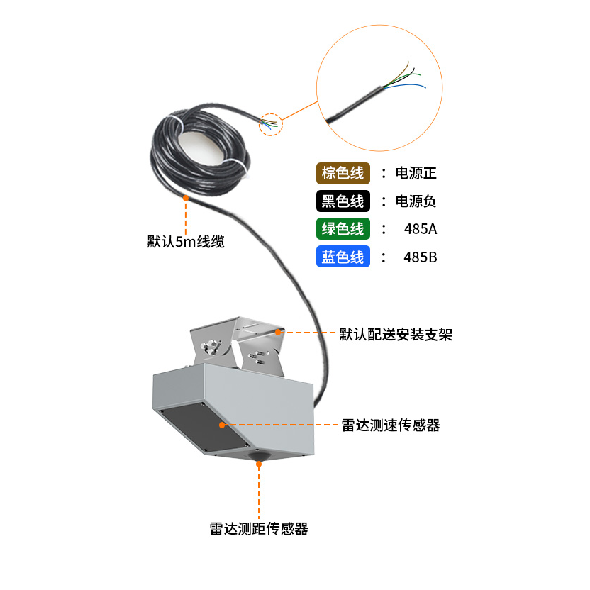
This second view shows radar velocity equipment and its wiring, rather than a refill controller. When several instruments feed one PLC or data logger, label each channel by quantity and unit. Commission the level channel independently before enabling valve commands or remote notifications.
No. It is often useful for an overflow system, but the correct location depends on hydraulic connections and the purpose of control. Test whether its level represents the reserve you intend to manage during occupancy changes and pump operation.
An RS485 measurement output is not a valve power output. A compatible controller must read the value and operate an appropriately designed actuator circuit. Confirm the register map, scaling and failure behavior.
Witness the start, stop and high-level conditions using a safe test procedure. Simulate a disconnected sensor and failure to recover level. Check maximum refill duration and the intended state after a power restart.
No. Suitability depends on the exact material, water chemistry, temperature and cleaning exposure. Request a compatibility review for the delivered model, including its cable and seals.
Include the hydraulic layout, minimum and maximum level, desired operating band, water chemistry and existing controller inputs. State whether mounting, valve control, local protection and remote reporting are included or supplied separately.
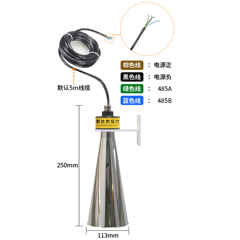
Select a pool water level sensor around the hydraulic arrangement and control duty. Floats can provide refill switching; continuous probes add trend information when properly configured. NiuBoL can assess a compatible level-measurement configuration, while the complete refill system must be tested for occupancy changes, invalid readings and valve faults.
Prev:Ultrasonic Water Level Sensor Limitations: Unstable, Fixed or Lost Readings
Next:Water Level Monitoring System Alarms: From Reading to Response
Related recommendations
Sensors & Weather Stations Catalog
 Agriculture Sensors and Weather Stations Catalog-NiuBoL.pdf
Weather Stations Catalog-NiuBoL.pdf
Agriculture Sensors Catalog-NiuBoL.pdf
Water Quality Sensor Catalog-NiuBoL.pdf
Related products
 Combined air temperature and relative humidity sensor
 TDR Soil Moisture & Temperature Sensor for irrigation| RS485 |4-20mA| NBL-S-THR
 Soil pH sensor RS485 soil Testing instrument soil ph meter for agriculture |NBL-S-PH
 Wind Speed sensor Output Modbus/RS485/Analog/0-5V/4-20mA
 Tipping bucket rain gauge for weather monitoring auto rainfall sensor RS485/Outdoor/stainless steel
 Pyranometer Solar Radiation Sensor 4-20mA/RS485


Screenshot, WhatsApp to identify the QR code
WhatsApp number:+8615367865107
(Click on WhatsApp to copy and add friends)

