

— Blogs —
—Products—
 Consumer hotline +8618073152920
WhatsApp:+8615367865107
Address:Room 102, District D, Houhu Industrial Park, Yuelu District, Changsha City, Hunan Province, China
Product knowledge
Time:2026-03-09 16:00:51 Popularity:765
Smart street light environmental sensor integration must account for how the pole is powered and controlled throughout the day. A sensor that works when the luminaire is on may stop when a switched supply is removed. Before designing the data connection, establish which circuits remain energized, what happens during lighting changes and whether the sensor and gateway share the same power availability.

A street-light cabinet may contain an unswitched supply, a switched lighting circuit and several regulated outputs. Their availability and electrical characteristics are not interchangeable. Have the responsible electrical designer identify an appropriate sensor supply and protective arrangement. Do not connect an environmental head directly to mains or an unsuitable lighting-driver output.
If the proposed DC bus exceeds the selected sensor's limit, an appropriate power conversion stage is required. Verify voltage at the sensor during normal loading and lighting transitions. A nominal cabinet voltage does not establish what reaches a long cable at the top of a pole, particularly when other services start or change load.
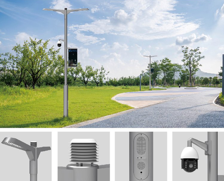
The lighting controller, environmental gateway and maintenance service need an agreed acquisition arrangement. Avoid two independent polling devices transmitting on the same serial segment without a designed coordination method. Give each sensor a unique address and keep the tested protocol settings with the pole's equipment record.
The sensor may communicate locally through RS485 Modbus RTU while the gateway uses a different upstream protocol. That conversion is a gateway function. Request a demonstration of the actual destination interface rather than assuming that a serial sensor natively provides cellular upload, Modbus TCP, MQTT or delivery to several platforms.
| Interface boundary | Question to settle | Useful commissioning evidence |
|---|---|---|
| Pole supply to sensor | Is the source continuous and within the selected voltage limits? | Measured voltage during lighting transitions |
| Sensor to serial host | Which device polls, and which register definition applies? | Saved request/response and decoded channel values |
| Gateway to platform | Which protocol, timestamps and unavailable states are delivered? | A received record and a simulated interruption |
| Maintenance to operations | Who restores configuration after replacement? | Accessible versioned settings and a tested restart procedure |

The NBL-W-71GUWS compact weather sensor is one possible pole-mounted measurement head. The configurable all-in-one family offers other channel combinations. Neither should be specified by a generic street-light bus voltage or by the largest channel count available in a brochure.
| Electrical or environmental item | Configuration basis | Integration implication |
|---|---|---|
| Supply | 9-24 VDC or 12-24 VDC version | Match the ordered version; do not assume 36 V compatibility |
| Local output | RS485 Modbus RTU | Provide a compatible host and the correct register mapping |
| Power demand | Average 0.4 W without particles; about 1 W with particles in the all-in-one family | Size the complete pole subsystem, including the gateway and losses |
| Protection and environment | IP65; -40 to 80 C; operating humidity 0-95% RH | Assess junctions, condensation and other equipment separately |
These figures apply to the linked configuration families, not every historic unit or accessory. The drawing of a multi-service pole illustrates an arrangement; it does not establish available supply capacity, structural approval or included environmental channels. Confirm the exact combination in the equipment schedule.

A memory device can retain earlier records without keeping a sensor operating. A gateway with backup power cannot collect a current value from a sensor whose supply has been removed. If the project requires continuous observation, both the sensing and acquisition paths need an appropriate power arrangement.
Determine the interruption the design must cover. A supply transition lasting seconds differs from hours without an energized circuit. For illustration, a complete sensor-plus-gateway load of 3 W needs 36 Wh over twelve hours before conversion losses and battery limits. That calculation is not a product load specification or proof that a small buffer battery is sufficient.
When supply returns, the host should wait for the sensor's required startup and stabilization period, confirm communication and mark the observation time correctly. Do not display yesterday's last reading as current while a unit is restarting. Specify this behavior in the gateway configuration rather than assuming that a sensor's internal reset mechanism provides it.
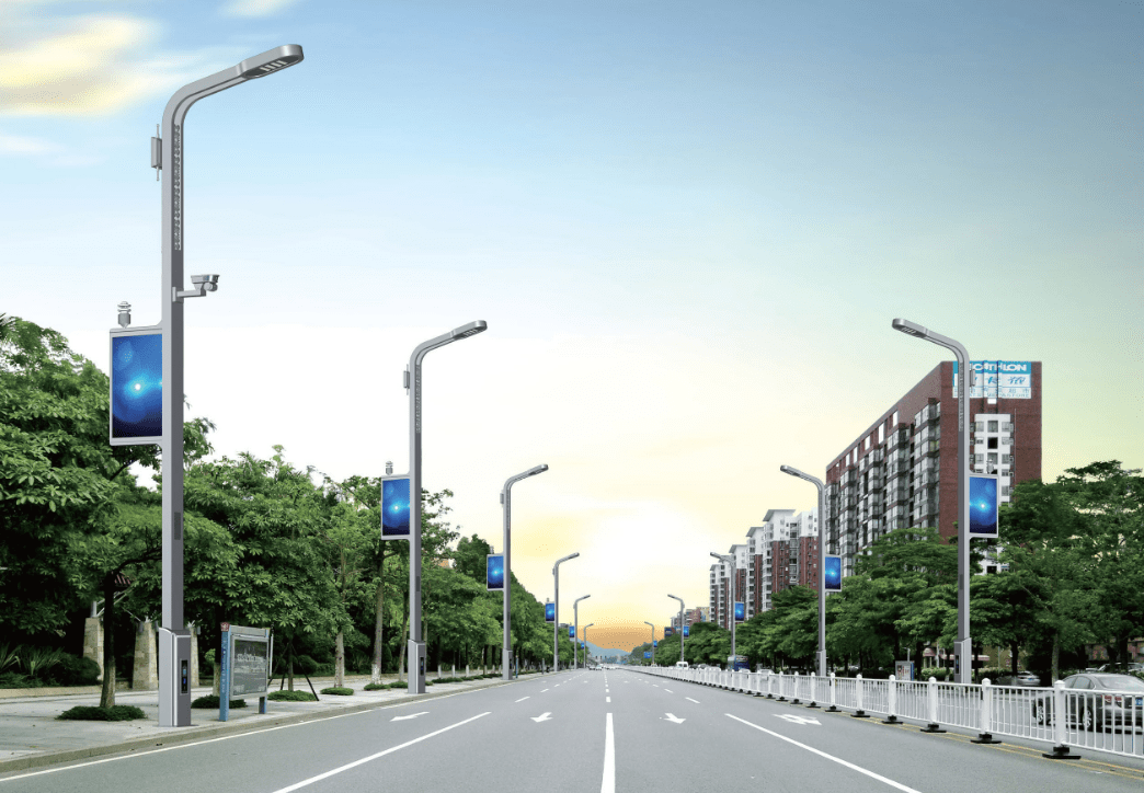
During commissioning, observe data and supply behavior while lighting is switched and other permitted loads change. If serial errors appear at the same moment, investigate power quality, cable routing and grounding arrangements before applying a software filter to the readings. Retaining error counts and event times helps distinguish interference from actual environmental variation.
Use appropriately designed segregation and protection for power and signal routes. An ingress rating does not establish surge immunity, and a shield connection is not a substitute for a coordinated grounding design. Electrical and structural work should follow the responsible designers' requirements for the actual pole and site.
If daylight switching is required, specify an illuminance measurement and a suitable control rule. Solar radiation in W/m2 is not the same quantity as Lux. A PM concentration is also not a direct visibility measurement. Avoid using a convenient weather channel as a substitute for the quantity the lighting or traffic application actually needs.
Define what the lighting controller does when an environmental channel is stale or unavailable. Test that state without disturbing live road operations. For particle trend monitoring, specify the intended interpretation and comparison checks; do not assume that pole-mounted PM readings automatically meet environmental enforcement or reporting requirements.
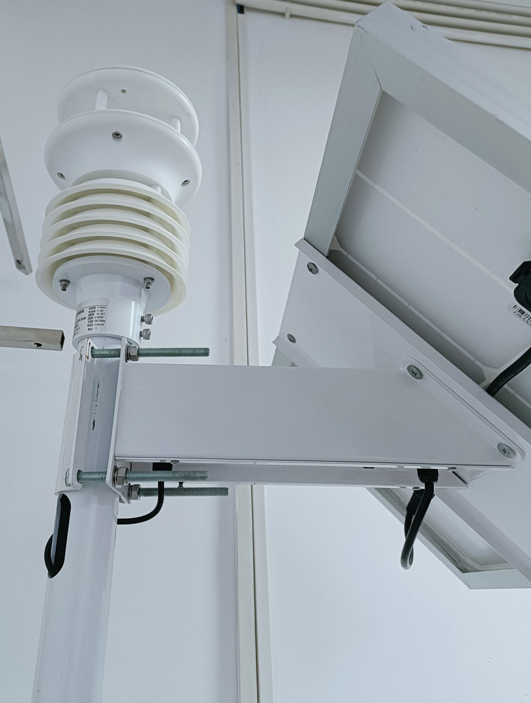
First verify the ordered channel list and bench decoding. Then verify the installed supply and serial path. Test lighting transitions, an upstream network interruption and a planned restart. Finally compare the platform record with the local acquisition time, including missing and recovered periods. Carry out electrical tests through authorized personnel and an approved site procedure.
For a NiuBoL quotation, provide the pole drawing, proposed supply, available continuous power, gateway model or interface requirements and required environmental channels. Include cable routes and service access. Ask separately for any backup power or historical recording function, so a sensor-only price is not mistaken for a complete continuously operating subsystem.
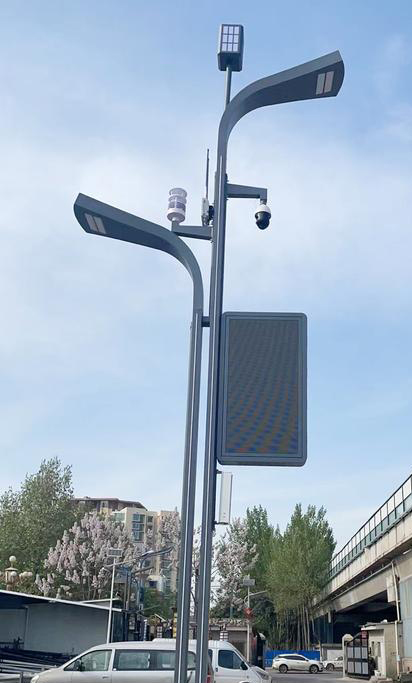
Only if an appropriate source remains available and meets the sensor's electrical requirements. A switched lighting circuit or driver output may not be suitable. The electrical design must identify the supply, conversion and protection needed for the actual sensor and gateway.
Storage can preserve records already acquired, but it cannot recreate observations that were never measured. Continuous monitoring requires power for the complete sensing path. Mark an unmeasured period as missing rather than filling it with a retained value.
Do not simply connect two independent polling hosts to the same segment. Use an acquisition arrangement designed for shared access, such as one host distributing records through a supported interface. Verify the actual architecture before installation.
The system should retain a clear distinction between continuous operation, restart and missing observations. Verify supply at the sensor, wait for the required startup behavior and accept new data only after communication and validity checks. The exact timings depend on the ordered equipment.
It provides selected measurements. Dimming requires a compatible controller and a defined rule, including unavailable-input behavior. Specify illuminance if that is the needed daylight quantity; do not assume an unrelated radiation or PM channel is an equivalent input.
Insufficient continuous power, unsuitable cable routes, inaccessible mounting and an incompatible gateway can add work. Survey these constraints before ordering. A compatible environmental head does not remove the need to adapt the existing pole infrastructure.
Smart street light environmental sensor integration depends on continuous power, clear serial-bus ownership and honest handling of missing observations. NiuBoL sensors can supply the selected measurements, while the pole designer and gateway configuration determine how reliably those measurements reach the city platform through lighting changes and interruptions.
Prev:Automatic Weather Station Benefits: When Automation Improves the Record
Next:Automatic Weather Station System Integration: Map Inputs to Platform Records
Related recommendations
Sensors & Weather Stations Catalog
 Agriculture Sensors and Weather Stations Catalog-NiuBoL.pdf
Weather Stations Catalog-NiuBoL.pdf
Agriculture Sensors Catalog-NiuBoL.pdf
Water Quality Sensor Catalog-NiuBoL.pdf
Related products
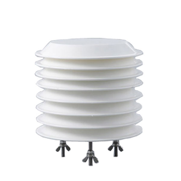 Combined air temperature and relative humidity sensor
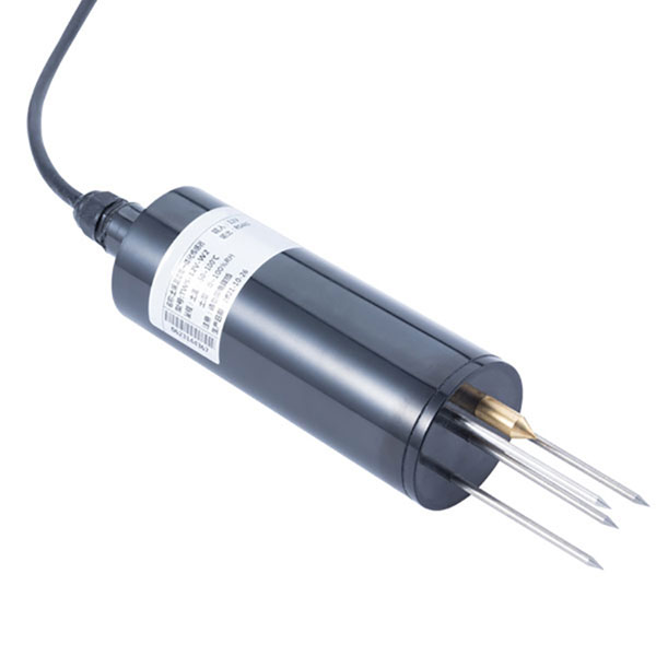 TDR Soil Moisture & Temperature Sensor for irrigation| RS485 |4-20mA| NBL-S-THR
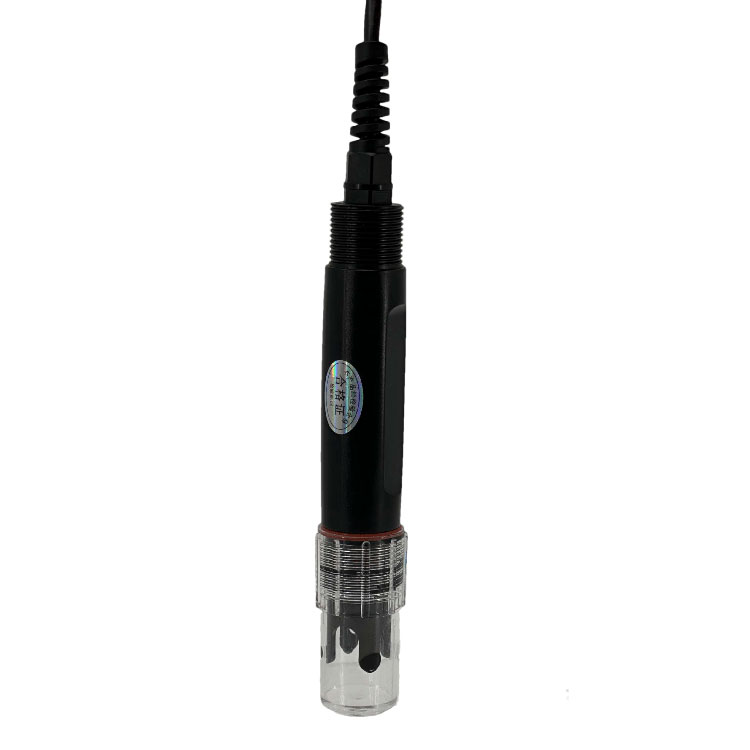 Soil pH sensor RS485 soil Testing instrument soil ph meter for agriculture |NBL-S-PH
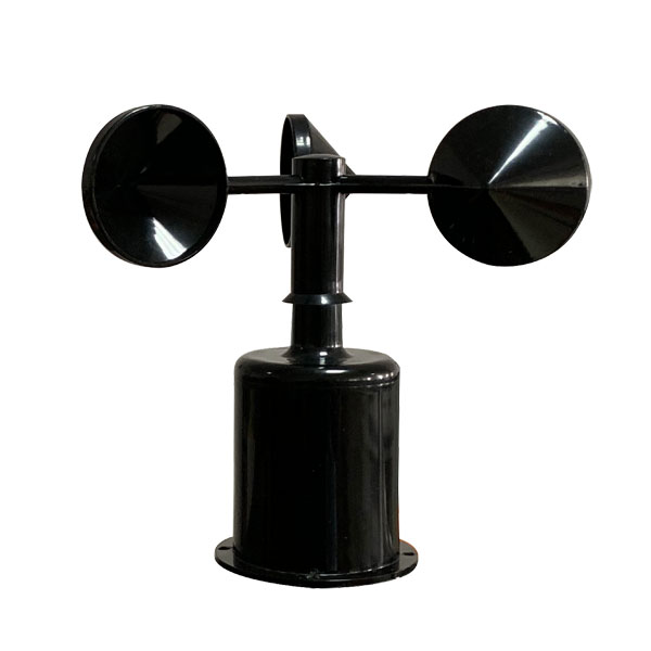 Wind Speed sensor Output Modbus/RS485/Analog/0-5V/4-20mA
 Tipping bucket rain gauge for weather monitoring auto rainfall sensor RS485/Outdoor/stainless steel
 Pyranometer Solar Radiation Sensor 4-20mA/RS485


Screenshot, WhatsApp to identify the QR code
WhatsApp number:+8615367865107
(Click on WhatsApp to copy and add friends)