





— Blogs —
—Products—
 Consumer hotline +8618073152920
WhatsApp:+8615367865107
Address:Room 102, District D, Houhu Industrial Park, Yuelu District, Changsha City, Hunan Province, China
Product knowledge
Time:2025-11-22 15:43:32 Popularity:826
Quick Answer: Compact ultrasonic weather station installation should start with exposure, orientation and the intended observation, not the smallest available bracket. Integration reduces the number of separate instrument bodies, but nearby roofs, walls and equipment can still distort readings. Select the actual channel configuration and verify its interface, power and maintenance access before fixing the mount.
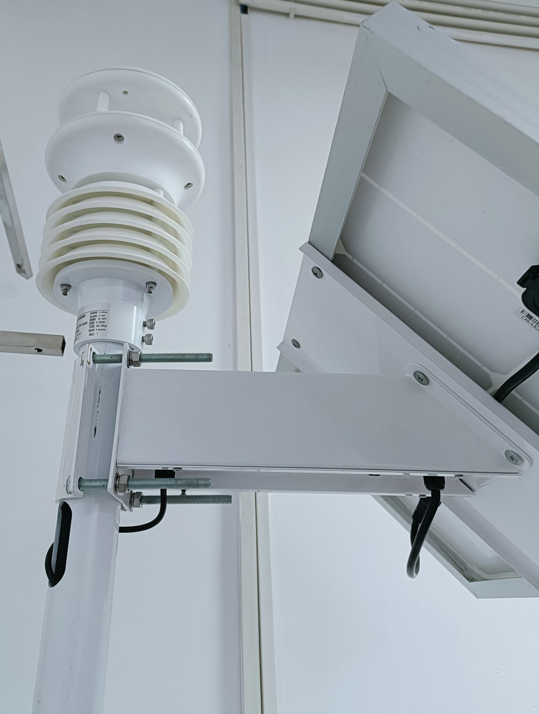
A rooftop point, an open agricultural reference and a sensor beside a road describe different environments. A compact sensor can fit all three mechanically while producing observations with different meanings. State whether the task is local microclimate monitoring or comparison with a reference exposure.
The unit above illustrates installation near a building surface. Assess airflow, reflected heat, radiation and obstructions at that position rather than treating physical clearance as proof of representative weather. Moving a bracket slightly above a parapet does not automatically remove the building's influence.
A single integrated head also puts several channels at one height and location. That can be useful for a local environmental point, but a project requiring separate exposure for wind, air temperature and rainfall may need a different arrangement. Compactness is a mechanical benefit, not a waiver of the measurement requirements.
A five-channel head and a larger configuration with rain or other modules do not share every specification. Confirm the exact model and parameter list. Do not assume that a compact wind sensor also measures irradiance, particulate matter or precipitation because another product in the family does.
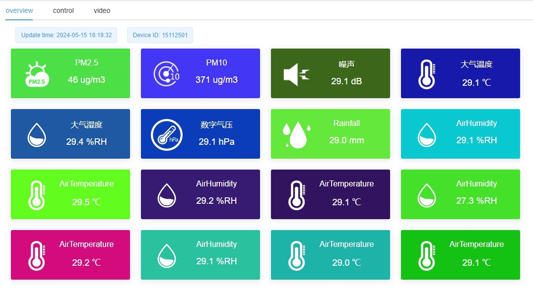
An ultrasonic head observes wind using acoustic transit times, while other fitted elements observe temperature, humidity, pressure or selected additional properties. The data logger receives and stores those outputs. A gateway or network function provides remote delivery where included.
The display can show more channels than a particular sensing head contains, especially in a modular station. Identify each physical source and channel mapping. Do not include an unused dashboard label in the equipment schedule as if it were a fitted measurement.
RS485 Modbus RTU can provide a suitable field connection for a configured NiuBoL head. Confirm its supply, serial parameters and actual register mapping with the intended PLC, RTU or logger. Remote mobile access requires additional implemented functions; it does not follow from the head's serial connector.
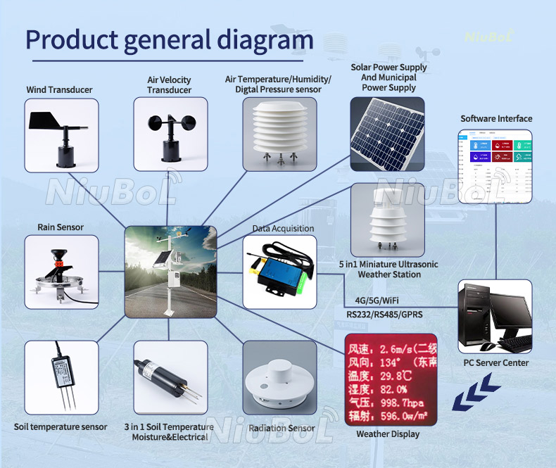
The NBL-W-51MUWS five-in-one option provides a concrete example. It measures wind speed, wind direction, air temperature, relative humidity and pressure. The larger or different heads illustrated elsewhere are separate configurations, so the following values must not be transferred to them automatically.
| NBL-W-51MUWS characteristic | Value | Installation consequence |
|---|---|---|
| Wind speed | 0-40 m/s; stated accuracy term +/-0.5 + 2% FS; 0.01 m/s resolution | Confirm the accuracy expression for the offered version; resolution is not minimum independently verified wind accuracy. |
| Wind direction | 0-359 degrees; +/-3 degrees; 1-degree resolution | Establish orientation and the receiving system's direction convention. |
| Air temperature | -40 to +100 degrees C measurement; +/-0.5 degrees C | Keep measurement range distinct from the complete head's operating limits. |
| Humidity and pressure | 0-100% RH, +/-5% RH; 10-1100 hPa, +/-1.5 hPa | Confirm which pressure quantity is stored; do not infer sea-level reduction. |
| Electrical | 12-24 V DC; average 0.3 W; RS485 Modbus | Include the logger and remote link separately in the supply budget. |
| Operating environment | -40 to +80 degrees C; 0-95% RH; IP65 | Check the complete field assembly and any exposed connectors. |
| Construction and cable | ABS; standard cable 2.5 m; cable jacket to be specified | Check mounting and cable reach without creating a strained or unprotected joint. |
A no-moving-parts wind path removes bearing and vane wear from that measurement, but it does not make the unit maintenance-free. Dirt, insects, moisture, icing, damage or an obstruction can still affect operation. Confirm whether heating is fitted and its actual limits rather than assuming all compact models are heated.
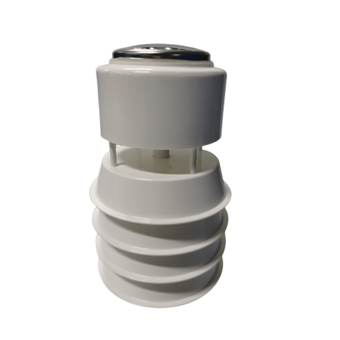
Identify the instrument's reference mark and align it to the project's chosen geographic reference. A magnetic compass can be affected by the steel mount or nearby equipment; magnetic and true north are not interchangeable. Use an appropriate orientation method and record what was applied.
If the receiving software applies a direction offset, keep that setting with the installation record. Do not apply the same correction in both sensor and platform. A fixed 90-degree orientation mistake can produce a consistent-looking direction series that points to the wrong sector.
Check the reported convention, including whether direction describes where wind comes from. Calm conditions may need a special interpretation because direction is less meaningful when airflow is very small. Do not diagnose orientation solely from an unstable near-calm reading.
Inspect the sensor head, bracket and cable routing from several directions. A cable, bird deterrent or nearby antenna can disturb the sensing region or airflow. Do not add an improvised cover over the head simply to protect it from rain; the cover can change the observation.
For an urban pole, review heat from luminaires or other equipment and the influence of nearby surfaces on temperature and humidity. For a field point, consider vegetation growth and agricultural operations. These checks should reflect the local task rather than an unsupported universal obstacle-distance rule.
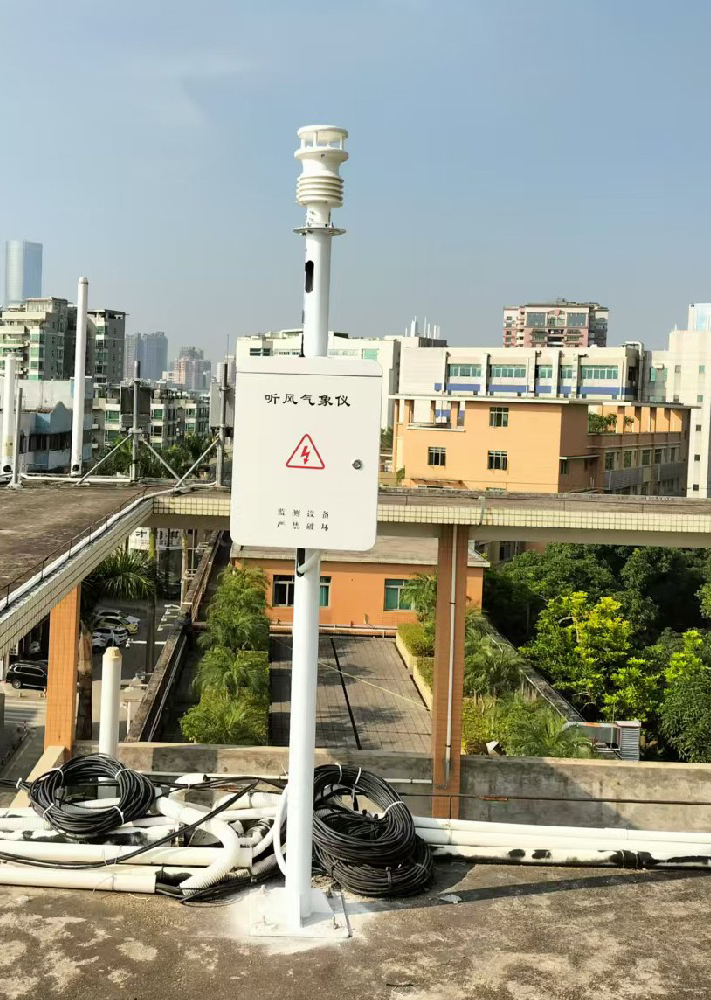
Verify voltage at the instrument under normal acquisition and representative station transmission. The supply at the cabinet may be adequate while a long or damaged cable causes a lower voltage at the head. Match cable identification to the supplied version rather than relying on another model's color scheme.
Read one physical head before connecting multiple devices to a bus. Check unique addresses, units, scaling and channel order, then inspect the receiving records. A plausible temperature value does not prove that wind direction or pressure has been mapped correctly.
Establish sampling and averaging definitions. A rapid serial read is not automatically an accepted gust statistic, and a platform refresh rate does not establish sensor response. Retain timestamps and validity so stale observations remain distinguishable during a network outage.
Wind direction is circular. For equally weighted directions of 359 degrees and 1 degree, a plain arithmetic average gives 180 degrees, which is opposite the near-north observations. An appropriate circular or vector method is needed for the intended statistic, with treatment of wind speed and calm conditions defined by the analysis.
A logger can therefore receive correct instantaneous directions and still publish a misleading average. Check the receiving calculation and interval before adjusting the instrument orientation. Retain the actual observations when diagnosing the difference, rather than assuming that a smooth wind-rose display proves correct processing.
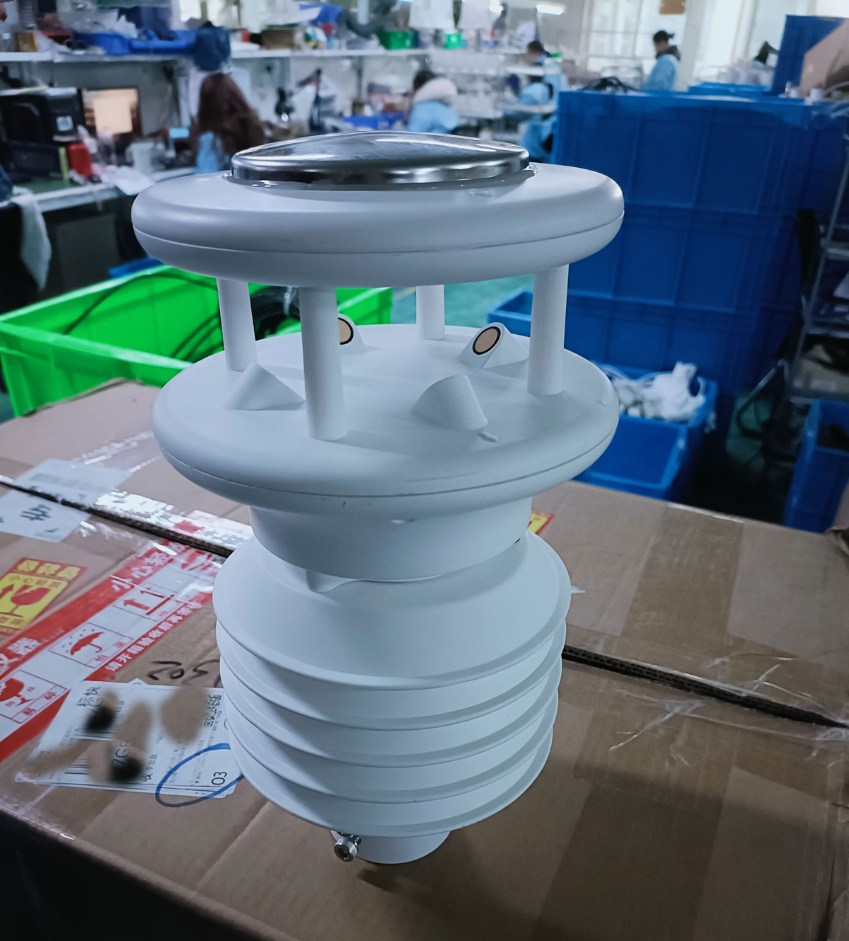
A compact head is convenient to transport, but monitoring should normally occur on a stable stationary mount. Measurements from a moving vehicle include motion and platform effects unless the intended system accounts for them. A fixed installation specification does not establish mobile wind capability.
When moving the station, repeat orientation, mounting and channel checks. Record the location and time of the change. A new roof or field position can produce a real step in the series even when the instrument is unchanged; do not remove it automatically as calibration drift.
For comparable observations between sites, assess whether the exposures and processing are compatible. A building-edge wind point and an open-site point can legitimately disagree. Increasing digital precision will not make those environments identical.
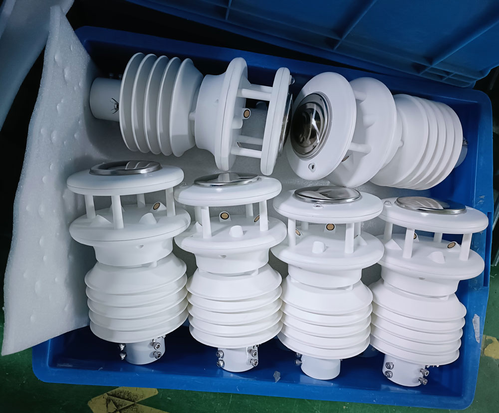
Inspect the head and mount, confirm orientation, acquire every ordered channel and verify unit and time definitions in the exported dataset. Check for obstructions, cable strain and safe maintenance access. A bench communications result should be followed by this installed check.
For a quotation, provide NiuBoL the intended location and measurement purpose, required channels, mounting arrangement and receiving interface. Include supply, cable distance and any heating or remote access requirement. Where the project needs separate exposure for particular measurements, state that before selecting an integrated head.
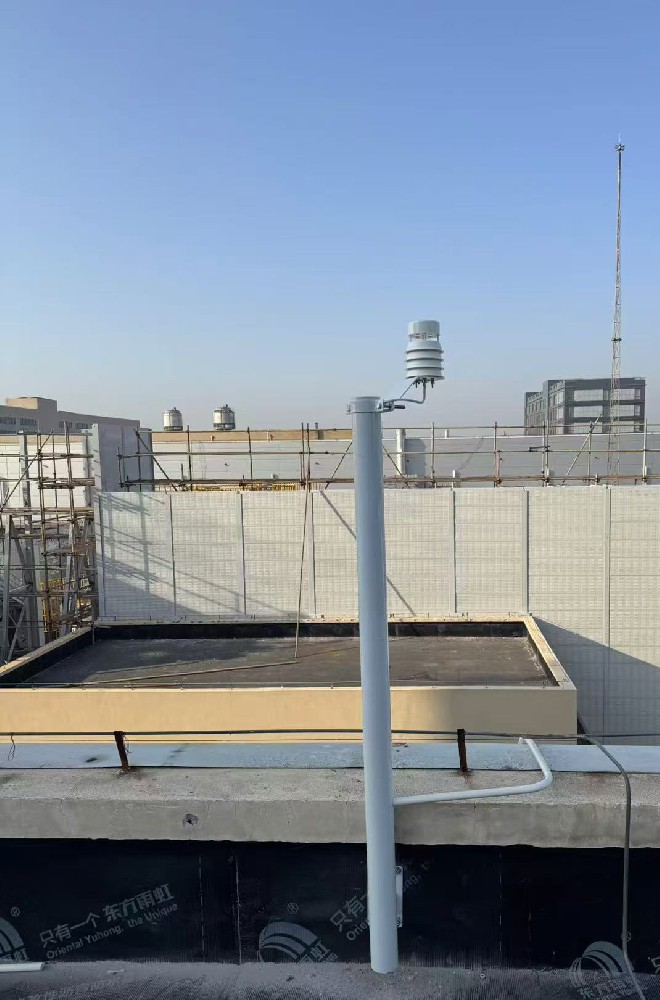
No. The location must represent the intended observation and provide suitable exposure. Roof edges, heat sources and obstructions can alter readings even when the mechanical installation is secure.
Not automatically. Identify the sensing head, acquisition and remote-delivery components separately. RS485 is not an internet connection.
No. Resolution is the reported increment. Use the model's actual accuracy expression and assess installed exposure and interpretation.
No. Different measurements and project methods can require different exposures. A co-located integrated unit may suit a local monitoring point but not every reference arrangement.
Not on the basis of its fixed-station specification. Operator or vehicle motion and surrounding obstructions affect the observation; a mobile application needs an appropriate method.
No. The wind measurement avoids rotating bearings, but the head, acoustic paths, fitted modules, cable and connectors still need inspection appropriate to the site.
Check exposure, mount stability, orientation, supply and acquisition, and record the new location and change time. Treat the new position as a changed observation setting, not an uninterrupted identical exposure.
A compact weather head is useful when its location and configuration match the observation. Confirm exposure and orientation, use the actual model's limits and separate sensing from data delivery. Good installation preserves the meaning of the measurements rather than merely reducing bracket size.
Related recommendations
Sensors & Weather Stations Catalog
 Agriculture Sensors and Weather Stations Catalog-NiuBoL.pdf
Weather Stations Catalog-NiuBoL.pdf
Agriculture Sensors Catalog-NiuBoL.pdf
Water Quality Sensor Catalog-NiuBoL.pdf
Related products
 Combined air temperature and relative humidity sensor
 TDR Soil Moisture & Temperature Sensor for irrigation| RS485 |4-20mA| NBL-S-THR
 Soil pH sensor RS485 soil Testing instrument soil ph meter for agriculture |NBL-S-PH
 Wind Speed sensor Output Modbus/RS485/Analog/0-5V/4-20mA
 Tipping bucket rain gauge for weather monitoring auto rainfall sensor RS485/Outdoor/stainless steel
 Pyranometer Solar Radiation Sensor 4-20mA/RS485


Screenshot, WhatsApp to identify the QR code
WhatsApp number:+8615367865107
(Click on WhatsApp to copy and add friends)

