





— Blogs —
—Products—
 Consumer hotline +8618073152920
WhatsApp:+8615367865107
Address:Room 102, District D, Houhu Industrial Park, Yuelu District, Changsha City, Hunan Province, China
Product knowledge
Time:2026-01-17 11:00:35 Popularity:809
Wireless level transmitter commissioning should prove three separate results: the instrument observes the intended level, the acquisition equipment interprets its output correctly, and the server receives a current record with the right identity. A working radio connection does not establish the first two. For a NiuBoL installation, keep these checks separate so a sampling, scaling or timestamp error is corrected at its source rather than hidden by a dashboard offset.
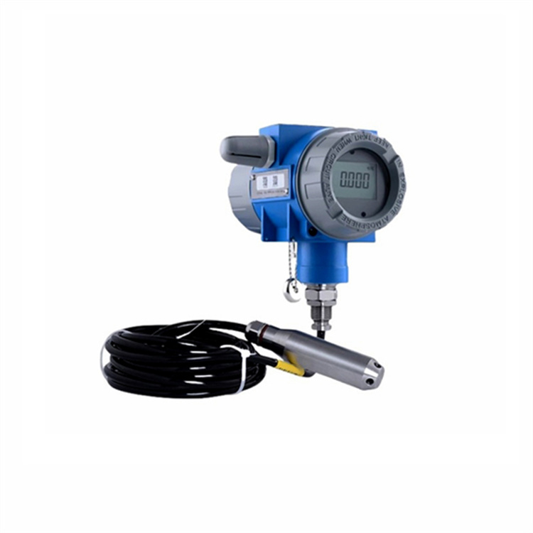
The NiuBoL NBL-L-SMP4601 split-type transmitter provides a wired 4-20 mA output and local display arrangement. A digital RS485 probe is a different interface. Neither becomes a self-contained cellular terminal merely because the receiving system includes an antenna or a similar display housing.
Match the terminal or gateway input to the ordered transmitter. For an analog loop, confirm loop power, input configuration, polarity and burden within the complete circuit. For an RS485 link, confirm voltage, wiring, device address, serial format and register map. The installer should have a point list naming the actual signal at each connection, not just a generic liquid-level tag.
| Signal path | Commissioning comparison | Typical interpretation error |
|---|---|---|
| 4-20 mA transmitter to analog input | Measured loop current, configured span and engineering value. | Wrong 0-20/4-20 mode, span or unit conversion. |
| RS485 Modbus RTU sensor to logger | Raw register, scale, unit and locally interpreted value. | Wrong address convention, numeric format or decimal position. |
| Logger or integrated terminal to server | Device identity, measurement time, value and quality state. | Correct number assigned to the wrong point or presented as newer than it is. |

For a hypothetical 0-5 m transmitter linearly mapped to 4-20 mA, 12 mA corresponds to 2.5 m: (12 - 4) / 16 x 5. This is a scaling example, not a statement that every supplied transmitter has that range. Verify the actual lower and upper range values and how the analog input reports an open loop or out-of-range current.
A Modbus value can also look plausible at the wrong scale. If the configured measurement uses three decimal places, a raw value of 101 represents 0.101 m, not 101 m or 1.01 m. Use the delivered sensor's scaling definition and compare a changing known observation, rather than assuming that a readable register is already an engineering value.
Retain the raw input and converted value during the test. If the local display, logger and cloud disagree, follow the first point where they diverge. Do not adjust the sensor zero merely to make a server graph resemble the local display. That can introduce a second error while leaving the original conversion fault in place.
Record whether the channel reports height above the diaphragm, depth from a tank floor or elevation relative to a surveyed reference. Note the probe's installed position and compare with an independent level observation using that same datum. A sensor supported above the bottom needs its elevation handled consistently; the cable length alone does not define the water-level reference.
For a vented hydrostatic probe, keep the reference termination dry and open through the intended protective arrangement. Check that cable glands, tight bends or storage loops do not crush the vent path. IP68 on the immersed sensor does not establish the protection of a field head, antenna joint or extension. Specify and inspect these parts individually.
Keep the pressure inlet clear of sediment and direct pump disturbance, with a mounting method that can be restored after service. Where a sleeve or stilling arrangement is used, demonstrate that water can enter and leave fast enough for the monitoring task. A steadier display is not necessarily a more faithful observation if the support arrangement delays actual level changes.

Confirm how the terminal obtains and retains time, including its time zone or UTC convention. Compare the locally stored measurement timestamp with the server record. A packet received now can contain an older observation, especially after a radio outage. The platform should not refresh the measurement's last-good time merely because the communications equipment is still connected.
Use a controlled sequence to test the route. Observe or simulate supported level inputs, note their times, then verify arrival order and units at the final platform. Clearly identify test data so it cannot trigger a real operational response. Where alarms are supplied, use the agreed test arrangement and confirm both acknowledgement and clearing behaviour.
State the permitted measurement age for the application. An hourly inventory update and a rapid high-level warning need different acquisition and delivery behaviour. The upload interval, retry policy and server processing should fit that requirement. A fast-refreshing screen cannot compensate for an old sample waiting in a device buffer.

Disconnect or disable the sensor through the approved test procedure while leaving the receiving terminal operational. Confirm that acquisition failure becomes visible and that the last valid value is not presented as current. An analog input needs its documented fault handling; a digital device needs timeout and invalid-response handling appropriate to the selected protocol.
Next interrupt only the uplink and check the ordered local storage and recovery behaviour. Local sampling may continue, but this has to be demonstrated. Restore communications and compare the returned records with the local sequence, including gaps, duplicate handling and timestamps. Do not assume that every wireless product has the same capacity or replay method.
Power interruption is a separate test. Verify the startup settings, point identity, clock and alarm state after restoration. When a device loses power, later replay cannot create the measurements that were never acquired. Record the interruption as an identifiable data interval rather than filling it with zero level or silently extending the previous value.
Store the accepted span, output type, scaling, addresses, serial settings and server tag against the instrument serial number and site location. Keep the wiring diagram and the installed level reference with that record. A replacement should be checked against these settings instead of configured from the appearance of the old display.
Record which parties own sensor calibration, gateway provisioning, server mapping and alarm delivery. A station can pass a local test while platform access is still incomplete. List unresolved items before handover and distinguish a temporary demonstration account from the receiving system the operator will use.
For an NiuBoL commissioning quotation, provide the selected sensor, controller or gateway, required span and units, level datum, antenna position and destination platform. Include the tests required after a sensor change or outage. This defines the service scope more clearly than a request to connect a wireless level meter and confirm that numbers appear online.

A hydrostatic level transmitter measures pressure-derived level. Discharge requires an appropriate hydraulic relationship or a separate velocity/flow instrument. A level channel should not be renamed as flow without that method.
No. Confirm the actual output and communications assembly. SMP4601 is a wired 4-20 mA option; any gateway or radio function must be explicitly included and matched to the input.
The receiver can read the wrong register, decimal position, unit or numeric format. Compare the raw data with a known changing observation and the accepted register map.
No. First identify datum, density, raw-signal scaling and timestamp differences. An offset can mask one operating point while leaving the measurement wrong elsewhere.
Do not block a vented probe's atmospheric reference. Use the required dry protective termination and preserve the vent path. Probe sealing and pressure reference have different functions.
A defensible physical level comparison, correct local conversion, matching current server records and tested failure/recovery states. A successful upload alone is only one part of that evidence.
Wireless level transmitter commissioning should trace one accepted observation from the liquid to the receiving platform. Match the NiuBoL output to the acquisition input, prove its scaling and datum, then verify timestamps and failure handling. Keeping those checks separate makes future replacement and diagnosis repeatable without changing good measurements to compensate for unrelated data faults.
Prev:Wireless Level Meter Battery Life: Uploads and Offline Recovery
Next:Wireless Level Monitoring System: Multi-Site Alarms and Service
Related recommendations
Sensors & Weather Stations Catalog
 Agriculture Sensors and Weather Stations Catalog-NiuBoL.pdf
Weather Stations Catalog-NiuBoL.pdf
Agriculture Sensors Catalog-NiuBoL.pdf
Water Quality Sensor Catalog-NiuBoL.pdf
Related products
 Combined air temperature and relative humidity sensor
 TDR Soil Moisture & Temperature Sensor for irrigation| RS485 |4-20mA| NBL-S-THR
 Soil pH sensor RS485 soil Testing instrument soil ph meter for agriculture |NBL-S-PH
 Wind Speed sensor Output Modbus/RS485/Analog/0-5V/4-20mA
 Tipping bucket rain gauge for weather monitoring auto rainfall sensor RS485/Outdoor/stainless steel
 Pyranometer Solar Radiation Sensor 4-20mA/RS485


Screenshot, WhatsApp to identify the QR code
WhatsApp number:+8615367865107
(Click on WhatsApp to copy and add friends)

