

— Blogs —
—Products—
 Consumer hotline +8618073152920
WhatsApp:+8615367865107
Address:Room 102, District D, Houhu Industrial Park, Yuelu District, Changsha City, Hunan Province, China
Product knowledge
Time:2022-09-12 08:56:54 Popularity:1868
Quick Answer: Restart remote precision irrigation by checking the field, not by enabling last season's schedule. Confirm that each sensor still represents its assigned zone, test actual water delivery under comparable operating conditions and verify recovery after power or network loss. A valve command, a flow reading and a soil-moisture response provide different evidence; use them together before releasing unattended operation.
Remote precision irrigation can appear ready because the dashboard reconnects and the stored programs are still present. Yet field conditions may have changed. Cultivation can move a soil probe, irrigation lines can be replaced, emitters can become blocked and a valve can be assigned to a different bed. A valid radio connection does not detect these physical changes.
Start with a walk-through using the current planting and irrigation layout. Mark each valve, flow point, pressure point and soil sensor on the same zone map. Compare that map with controller labels. Check whether a pipe repair has changed which area a valve actually supplies. An accurate moisture reading from the wrong zone is particularly misleading because it may look entirely plausible.
Keep automatic schedules disabled while commissioning unless a controlled test explicitly requires them. Coordinate pump and valve work with responsible staff, and use approved electrical and hydraulic isolation procedures. Do not test a protection function by deliberately running equipment in a damaging condition. A seasonal restart is a controlled return to service, not a sequence of remote commands issued without field supervision.
A sensor left in place after harvest may be in compacted soil, beside a new wheel track or outside the active wetting zone. Inspect its depth, position relative to the emitter and contact with the surrounding soil. Air gaps and disturbed soil can change the reading. Record any relocation so a discontinuity is not mistaken for an abrupt change in the field's water condition.
Place observation points to answer a specific question. A sensor near an emitter can show local wetting but may not describe the drier edge of the root zone. A deeper point can help track downward movement, but it cannot reveal every lateral dry area. Where soil or irrigation distribution varies, additional representative points are more useful than several sensors concentrated in the easiest location.
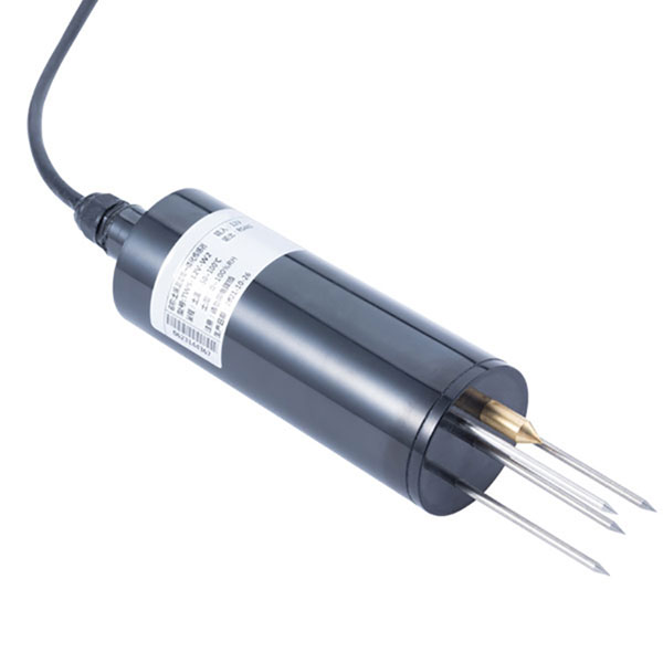
The NiuBoL NBL-S-THR soil temperature and moisture sensor provides two measurements that can be recorded by a compatible acquisition system. It is a sensing component, not a valve controller. Use its soil moisture trend alongside delivery observations, crop stage and local agronomic decisions rather than treating one percentage as a universal irrigation instruction.
| Parameter | NBL-S-THR value | Restart check |
|---|---|---|
| Soil moisture range | 0-100%; resolution 0.1%; stated accuracy +/-3%. | Verify contact and representative location. Do not interpret a display increment as installed accuracy. |
| Soil temperature range | -50 to +100 degrees C; resolution 0.1 degrees C; accuracy +/-0.5 degrees C. | Check that temperature and moisture channels have not been interchanged. |
| Power supply | 12-24 V DC. | Check voltage at the field connection, not only at the enclosure. |
| Output options | RS485 Modbus RTU, 4-20 mA or 0-5 V, selected by configuration. | Match the installed version to the receiver and its scale. |
| Power consumption | Approximately 0.3 W. | Include the controller, modem and valve equipment separately in the power budget. |
| Operating environment | -40 to +80 degrees C. | Distinguish the operating limit from the temperature measurement span. |
| Protection | IP68. | The probe rating does not establish the protection of field splices or the control cabinet. |
| Cable specification | Confirm length and jacket material for the ordered assembly. | Inspect burial routes, cultivation damage, strain relief and terminations. |
For an analog version, verify the configured conversion after any controller replacement. The 4-20 mA moisture channel maps across 0-100%, while the temperature channel maps across -50 to +100 degrees C. At 12 mA these represent 50% and 25 degrees C respectively. This is a channel-scaling check, not proof that the soil actually has either condition.
Open one identified zone under the intended test arrangement and observe where water appears. Record the water source, pump condition, filter condition, open valves and relevant pressure readings. Compare flow only when those conditions are sufficiently similar. A block operated alone and the same block sharing a pump with several others may not have the same flow.
Use a measured flow baseline rather than a nominal emitter total alone. For an illustrative calculation, a zone previously delivering 12 m3/h under matched conditions now records 9 m3/h. That is a 25% reduction. Over half an hour, the corresponding volumes are 6 m3 and 4.5 m3. The example quantifies the difference; it is not a reported NiuBoL result or a universal alarm threshold.
Before increasing runtime to recover the apparent shortfall, find its cause. A restricted filter, changed pump operation, a partially closed valve, blocked emitters, an inaccurate flow channel or a different active-zone combination can all alter the reading. Extra runtime may conceal a distribution fault while leaving some plants dry and overwatering others.
| Observed pattern | Possible investigation | What the reading does not prove |
|---|---|---|
| Lower flow with lower pressure at a comparable point | Check available supply, pump operation and restrictions upstream of that pressure point. | It does not uniquely identify a failed pump. |
| Lower flow with normal or higher upstream pressure | Check downstream valve opening, filters and emitter blockage, considering where pressure is measured. | It does not locate a blockage without additional inspection. |
| Flow after all intended zones have closed | Allow for expected transients, then inspect unintended outlets, leakage, valve seating and the flow zero. | It does not establish which valve or pipe is responsible. |
| Normal aggregate flow but an unevenly wetted block | Inspect distribution, lateral condition and representative emitter delivery. | A mainline total does not prove uniform application. |
Record pressure-point locations with the readings. A pressure upstream of a restriction and one downstream answer different questions. Use appropriately rated test fittings and qualified personnel; do not loosen a pressurized connection to create a test point. The commissioning record should let the next technician reproduce the comparison without guessing the hydraulic arrangement.
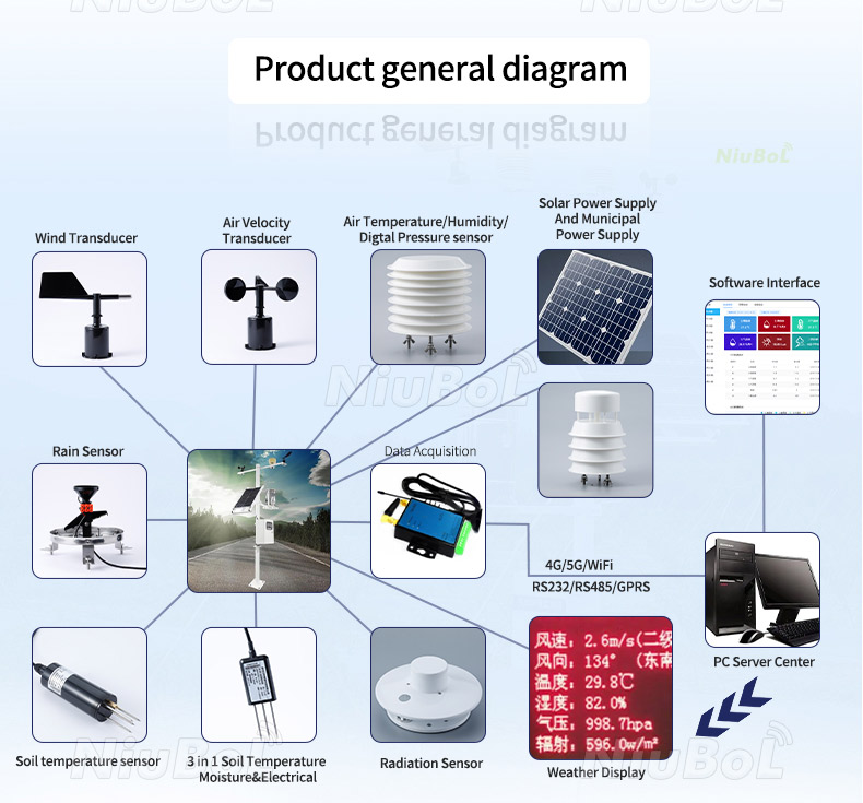
The architecture diagram illustrates the path from field observations to remote supervision. It does not mean every gateway can drive every valve. Keep the responsibilities clear: sensors report conditions, the controller executes permitted actions, and flow or pressure measurements help check physical delivery. The remote interface should show which of these has actually been observed.
During a supervised watering test, confirm that the commanded zone is the one receiving water. Then watch the expected wetting response at representative soil points. The response may be delayed by sensor location, soil structure, emitter placement and initial conditions. A deeper probe need not rise at the same moment as a shallow point. Determine an appropriate observation window for the site rather than importing a fixed delay from another farm.
If flow is present but the selected moisture point does not change, first inspect the wetting pattern and sensor contact. Do not keep extending irrigation indefinitely until one probe crosses a target. The sensor may lie outside the wetted volume, or water may be bypassing it. A physical soil check and a comparison point can separate those situations more effectively than another remote command.
A successful connection beside the enclosure does not establish performance with the field loads operating. Check supply behavior with the intended controller, modem and actuators in service. Inspect battery condition, charging connections and solar-panel exposure where applicable. A system that reboots during valve operation needs a power investigation, not simply a longer network retry period.
For RS485 Modbus RTU sensors, confirm the address list, serial settings and channel labels after replacements. For the remote link, test at the deployed antenna position and consider changes in crop height or nearby structures. Record acquisition time separately from transmission time so delayed uploads are not presented as new soil measurements.
Temporarily interrupt the network in a supervised test. Check what remains under local control, how missing observations are displayed and what happens after reconnection. Pending commands need explicit expiry and recovery rules in the control implementation. A recovered internet connection must not cause old watering requests to be executed unexpectedly.
At the start of each season, test every zone and safety input before relying on automatic mode. Confirm source-water conditions, exercise valves, compare flow, inspect batteries and solar panels, review alarm recipients and verify time settings. Remote access does not replace this field inspection. Check that the responsible operator can identify the physical zone from the screen label.
Review settings against the current crop stage, soil observations and irrigation arrangement. Retain changes to moisture thresholds, permissible watering periods and maximum runtime with dates and reasons. The correct value is a site decision, not a factory-wide percentage. Separate an intentional seasonal adjustment from a correction made because a probe was moved or a valve label was wrong.
When purchasing replacement instruments, provide NiuBoL with the existing controller input, sensor model, supply, cable route and observed fault. Replace a sound sensor only after checking contact, wiring, scaling and delivery conditions. Where additional flow, pressure or control equipment is needed, request a configuration-specific compatibility check; a soil probe or communication gateway alone does not supply all those functions.
Yes, before returning the system to unattended seasonal operation. A healthy communication channel does not reveal a swapped valve label, blocked lateral or probe moved during cultivation. Confirm zone identity and water delivery in the field.
Only after the cause and distribution have been checked. A longer runtime may be appropriate for a deliberate flow change, but it can worsen uneven watering caused by blockage or leakage. Compare matched operating conditions before changing the schedule.
No. It confirms a response near that probe under its installation conditions. Inspect representative parts of the block and compare suitable observation points. Mainline flow and one wet probe can both look normal while other areas remain under-watered.
They can be reviewed as a starting point, but should not be enabled without checking crop stage, probe position, soil condition and any hydraulic changes. Record the basis for retained or revised settings so later troubleshooting has context.
The defined local control and protection should remain effective, while unavailable or stale observations are identified. Recovery must not replay expired watering commands. Test this behavior in the actual controller implementation; do not assume it is provided by a sensor or modem.
Keep an updated zone map, probe locations, matched-condition flow and pressure baselines, setting changes and unresolved defects. Include the date and operating arrangement for each test. A flow number without its active-zone and pressure context is difficult to reuse.
Seasonal restart of remote precision irrigation is a practical comparison between the map, the measured delivery and the soil response. Verify those three before reusing automatic schedules. Compatible NiuBoL sensing components can support the observations, while the complete control arrangement must demonstrate safe, repeatable operation in the field.
Related recommendations
Sensors & Weather Stations Catalog
 Agriculture Sensors and Weather Stations Catalog-NiuBoL.pdf
Weather Stations Catalog-NiuBoL.pdf
Agriculture Sensors Catalog-NiuBoL.pdf
Water Quality Sensor Catalog-NiuBoL.pdf
Related products
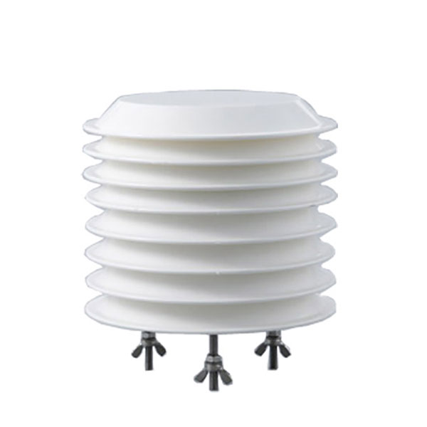 Combined air temperature and relative humidity sensor
 TDR Soil Moisture & Temperature Sensor for irrigation| RS485 |4-20mA| NBL-S-THR
 Soil pH sensor RS485 soil Testing instrument soil ph meter for agriculture |NBL-S-PH
 Wind Speed sensor Output Modbus/RS485/Analog/0-5V/4-20mA
 Tipping bucket rain gauge for weather monitoring auto rainfall sensor RS485/Outdoor/stainless steel
 Pyranometer Solar Radiation Sensor 4-20mA/RS485


Screenshot, WhatsApp to identify the QR code
WhatsApp number:+8615367865107
(Click on WhatsApp to copy and add friends)